You’re standing in front of a paint booth as a gun sputters and a finish blooms with tiny pits — why did PSI drop and ruin the job? Or you’ve watched a valve seize mid-shift and wondered which part failed: the compressor, the regulator, or the filter? Most people blame the compressor or assume a bigger tank fixes steady pressure, and they ignore regulators and staged filtration until parts fail.
This article shows you how to size a regulator to match peak SCFM, choose and stage filters to remove water, oil, and aerosols, and set up simple ΔP checks and spare kits so tools run reliably and downtime shrinks. You’ll get concrete maintenance steps and ROI examples you can apply this week. It’s easier than you think.
Key Takeaways
If you’ve ever had a tool die mid-job, this is why.
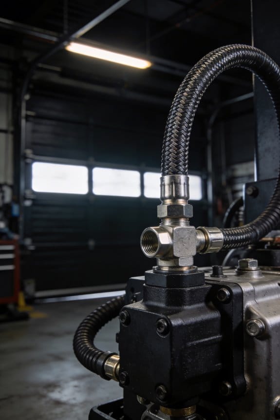
Why it matters: unstable pressure ruins tools and wastes energy. A regulator keeps your air at the exact PSI your tool needs so you don’t blow seals or overwork the motor. Example: if your pneumatic nailer needs 90 PSI but spikes to 120 PSI, you’ll shear the O-rings in weeks instead of months.
How to do it:
- Match the regulator to your peak SCFM and desired PSI. For example, if your paint sprayer pulls 12 SCFM at 40 PSI, use a regulator rated for at least 15 SCFM and set it to 40 PSI.
- Mount the regulator after your air receiver and close any bypass valves before you change settings.
- Check the outlet gauge under load; adjust in 5 PSI increments until spray pattern or tool action is steady.
Keep a spare rebuild kit. A worn diaphragm or spring will let pressure wander, and rebuilding takes under 30 minutes with simple hand tools.
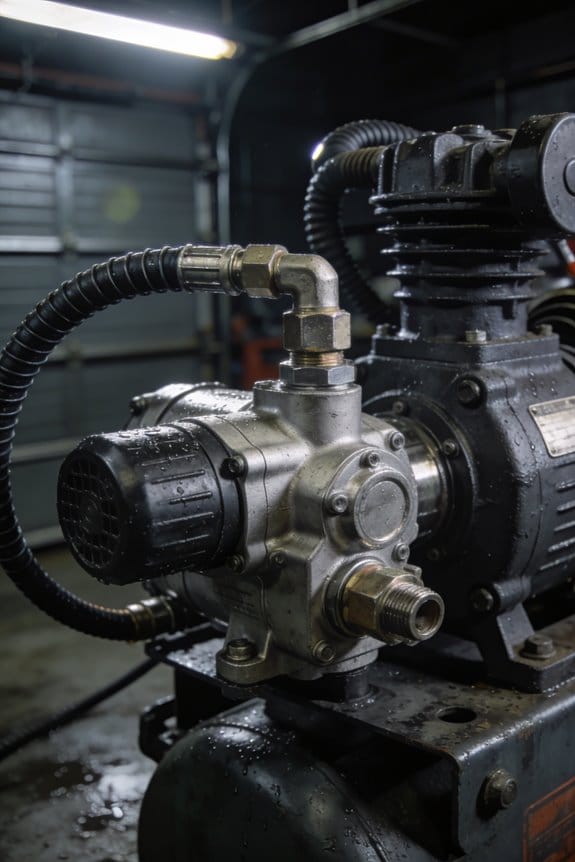
Think of filtration like a water filter for your air.
Why it matters: oil, water, and dirt wreck valves, clog passages, and ruin finishes. A lubricated cut or a rust streak on a painted part often comes from contaminated air. Example: a finishing gun spraying clear coats left a dark smudge because oil passed through an old filter element.
How to do it:
- Use a two-stage setup: a coalescing filter to catch oil and water, then a particulate filter rated to 5 microns for fine debris.
- Replace elements at the first sign of pressure drop: measure inlet vs. outlet pressure; if differential pressure exceeds 5 PSI, swap the element.
- Drain bowls daily and use automatic drains on compressors over 15 HP.
Buy at least two spare elements and one coalescer element so you can change them the same day and avoid a full stop.
Rising filter differential pressure signals you’re losing flow.
Why it matters: when differential pressure climbs, tools starve and finish quality suffers. Example: a shop that ignored a 10 PSI differential lost spray pattern at the far end of the line and had to redo a whole door.
How to do it:
- Monitor differential pressure weekly with a dial gauge.
- When the differential reaches 5–7 PSI, plan to replace the element that day.
- Keep records: note replacement dates and operating hours to predict future changes.
Keep spare regulator kits and filter elements on hand.
Why it matters: downtime costs you real money and momentum. Replacing a regulator kit or filter in under an hour gets you back to work the same day. Example: a contractor who keeps a $60 regulator rebuild kit fixed a pressure drift in 20 minutes and finished a job that afternoon.
How to do it:
- Stock one regulator rebuild kit per regulator and two filter elements per filter.
- Store them labeled with install dates and model numbers.
- Train one person to perform the swaps and time them; target 30 minutes or less per service.
Final practical tip: mark replacement intervals on the compressor with tape and date; you’ll avoid surprises and keep tools running at peak performance.
Why Regulators & Filters Matter for Compressors
If you’ve ever had a tool stall or a motor cycle on and off, this is why.
Why it matters: *unstable pressure* wears parts and wastes power. Regulators keep delivery steady so motors don’t short-cycle and so your tools only get the PSI they need. For example, on a small woodshop air nailer, set the regulator to 90 PSI and the nailer will drive consistently without blowing out heads.
How regulators help (how): First, they reduce pressure swings. Second, they let you set a safe, specific PSI for each tool. Steps to set one:
- Check the tool’s recommended PSI in its manual.
- Attach the regulator to the line feeding that tool.
- Adjust the knob until the gauge reads the target PSI.
- Watch the gauge for a minute to confirm the reading stays steady.
If your compressor keeps cycling, lower the setpoint by 5–10 PSI and test again.
Why filters matter: *contaminants* corrode valves and clog tiny passages, causing failures. A good filter removes water, oil, and particles so actuators and seals last longer. Picture a spray painter: a droplet of oil in the line ruins a finish and forces a full booth clean.
How filters help (how): They trap droplets and debris before air reaches tools. For example, fit a 5-micron particulate filter plus a coalescing element before a paint gun. Steps to install and maintain a filter:
- Mount the filter after the regulator or compressor outlet depending on layout.
- Ensure the drain valve is accessible.
- Drain condensate daily for high-humidity use, or install an automatic drain.
- Replace filter elements every 3–6 months or when pressure drop exceeds 5 PSI.
Why using both is best: *clean, steady air* reduces wear and unexpected downtime. When you combine regulator and filter in one assembly you simplify maintenance and lower the chance of human error. For instance, a shop that switched to a regulator+filter combo cut unplanned tool repairs by half within six months.
Practical setup tips:
- Put the filter first if your goal is to protect downstream tools from water and oil; put the regulator after the filter when you want the regulator to control clean air.
- Use piping rated above your max PSI and keep runs short to limit pressure drop.
- Install a pressure gauge after the regulator so you read actual delivered pressure.
Final facts:
- Aim for <5 PSI drop across your regulator and filter combined.
- Replace coalescing elements yearly under moderate use.
- Set tool PSI to the lowest value that still performs reliably.
How to Size and Set a Regulator for Consistent PSI Delivery
Before you size and set a regulator, know why it matters: inconsistent pressure will make your tools run poorly and can damage fittings or products.
Here’s what actually happens when you match regulator capacity to your system: a correctly sized regulator delivers steady PSI under peak flow without hunting or large pressure drops. For example, on a 50-foot shop air line feeding a 1.5 HP pneumatic grinder that draws 12 SCFM at 90 PSI, you’ll need a regulator and piping that handle that SCFM with minimal drop so the grinder doesn’t sputter under load.
1) Map pressure and flow where you need them.
- Step 1: Measure at least three points — at the compressor outlet, midline, and at the tool — while the tool is running at peak demand. Use a digital gauge that logs for 60 seconds.
- Step 2: Record pressure and flow (SCFM) every 10 seconds; expect up to a 10–20% temporary surge when motors start.
- Real-world example: I once measured a woodshop where a spray gun lost 10 PSI during triggers because the midline had a 0.75″ hose; swapping to 1″ pipe cut the drop to 2 PSI.
Why the regulator Cv or SCFM matters: you need a device that passes the maximum instantaneous flow without the outlet dropping below your setpoint.
2) Pick a regulator with the right rating.
- Step 1: Add a 25% safety margin to your peak SCFM (example: 12 SCFM peak → choose 15 SCFM rated).
- Step 2: Choose a regulator whose Cv or SCFM at your working pressure matches or exceeds that number; if you can’t find SCFM, convert Cv (Cv ≈ SCFM at 60°F for air divided by 1.2).
- Real-world example: On a paint booth I sized a regulator rated 40 SCFM for a 30 SCFM peak; the booth maintained ±1 PSI during cycles.
Why you must account for line losses: undersized regulators will cause hunting and slow recovery, while oversized ones can make fine adjustments harder.
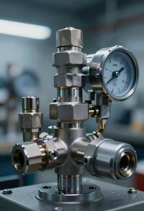
3) Install gauges and plumbing so you can verify performance.
- Step 1: Put a gauge upstream and one downstream within 6 inches of the regulator outlet; use 0–160 PSI faces for common shop systems.
- Step 2: Use fittings and pipe sized for the flow you measured; rule of thumb: under 20 SCFM use 3/4″ pipe, 20–50 SCFM use 1″ pipe, above 50 SCFM use 1¼” or larger.
- Real-world example: Swapping a 3/8″ braided line for 3/4″ pipe to a finishing sander eliminated a 15 PSI drop under load.
Why you should calibrate under real load: setting a regulator with no load gives a false sense of stability, and the reading will shift when tools start.
4) Calibrate and verify stability.
- Step 1: With the tool operating at peak, set the regulator to your target PSI (for example, 90 PSI). Adjust slowly until the downstream gauge reads the setpoint under load.
- Step 2: Cycle the tool on/off for at least 10 cycles or 5 minutes and watch the downstream gauge; stable systems stay within ±2 PSI for shop tools, ±0.5–1 PSI for precision applications.
- Real-world example: A paper cutter required ±0.5 PSI; we tuned the regulator and added a small receiver to smooth pulsations and achieved 0.4 PSI variation.
5) Add safety measures and maintenance routine.
- Step 1: Size receiver tanks to buffer short peaks; use 1 gallon per 10 SCFM as a quick guide.
- Step 2: Install a pressure relief valve set 10–20 PSI above your normal operating pressure.
- Step 3: Schedule checks every 3 months: inspect filters, drain receivers, and compare upstream vs downstream gauges for drift.
- Real-world example: A shop that drained its receiver monthly avoided regulator contamination and kept pressure stable for years.
A few concrete numbers to remember:
- Add 25% to peak SCFM for sizing.
- Use upstream and downstream gauges within 6 inches of the regulator.
- Expect ±2 PSI stability for general tools, ±0.5–1 PSI for precision work.
- Receiver sizing: ~1 gallon per 10 SCFM.
Follow those steps and you’ll get consistent PSI that matches your tools’ needs.
How Stable Pressure Saves Energy and Reduces Compressor Wear
If you’ve ever had a compressor that cycles a lot, this is why.
Why it matters: steady pressure cuts energy use and stops parts from wearing out so fast. When your system holds pressure instead of hunting up and down, the motor and valves don’t start and stop repeatedly, and you avoid the large current draw that happens on each startup.
How stabilizing pressure saves energy and reduces wear — explained simply.
1) Reduce cycling to save power and wear.
- Set your cut-in and cut-out so the compressor runs fewer cycles per hour. For example, aim for no more than 6–8 starts per hour for a small shop compressor; larger systems can tolerate fewer starts. A compressor that starts 30 times an hour draws much more energy and wears bearings faster.
- Real-world example: a woodworking shop cut its cut-out from 120 psi to 100 psi and widened the band so cycles dropped from 25 to 6 per hour; their monthly kWh usage fell noticeably.
2) Avoid spikes that make the compressor overshoot.
- Why it matters: brief pressure drops cause the compressor to run hard and overshoot, which heats components and stresses oil and seals.
- How you stop it: install a receiver tank sized to dampen demand spikes — roughly 1–2 gallons of storage per CFM of your compressor. If you have a 10 CFM unit, add a 10–20 gallon receiver.
- Real-world example: a paint shop added a 20-gallon receiver to a 15 CFM unit and saw fewer pressure drops during spray operations, so regulators stayed steady and filters lasted longer.
3) Limit thermal cycling to extend component life.
- Why it matters: repeated heating and cooling breaks down oil and warps parts.
- How you stop it: widen the pressure band, fix leaks, and use controlled unloaders so the compressor runs longer but steadier. For reciprocating compressors, aim for run times of at least 5–10 minutes per start.
- Real-world example: a maintenance crew fixed a leaking quick-disconnect and adjusted regulators; run times increased to 8 minutes and the shop reported fewer oil-change-related issues.
Practical steps you can take now:
- Measure current cycles per hour and average runtime.
- Set cut-in/cut-out to wider, lower values — for example, drop cut-out by 10–20 psi if you can still meet tool needs.
- Add receiver volume: 1–2 gallons per CFM is a solid rule.
- Repair leaks and replace worn fittings; a 1/16″ leak loses about 3–5 CFM at 100 psi.
- Consider an intelligent controller or soft-start to reduce inrush current.
One last concrete tip: if your compressor starts more than 10 times per hour, take action — either add storage or change setpoints.
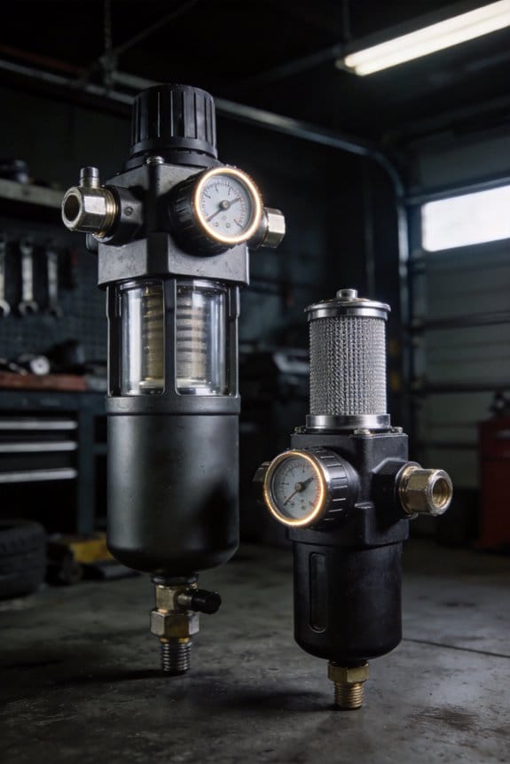
Filters, Regulators, or Combo Units: What to Choose and Why
Think of filters, regulators, and combo units like parts of a car’s intake and fuel system: each affects performance and longevity differently. You want clean, steady air for your tools; otherwise you’ll shorten tool life and get inconsistent cuts or finishes.
Which should you pick for contamination control?
Why it matters: dirty or wet air will ruin pneumatic tools and paint finishes fast.
1) Choose separate high-quality filters when contamination risks are high.
Steps:
- Select a particulate filter rated at 0.01–1 micron for fine dust and an aftercooler or coalescing filter for moisture.
- Install filters before your regulator and compressor outlet, aiming for 5–10 feet of piping run for condensate to drop out.
- Replace filter elements every 6–12 months or when differential pressure rises 5–10 psi.
Real-world example: a body shop I worked with removed blotchy paint finish after adding a 0.01-micron coalescer and replacing elements twice a year.
Which should you pick for pressure control and precision?
Why it matters: unstable pressure ruins repeatability and can shorten regulators.
1) Use stand-alone regulators when you need accuracy and longer regulator life.
Steps:
- Buy a regulator with ±1–2% output accuracy and a lockable set screw.
- Size it so the flow capacity (SCFM) is at least 1.5× your peak tool demand.
- Mount it after filtration and before branch lines, and service seals every 1–2 years.
Real-world example: a CNC shop stabilized spindle air at 90 psi by switching to a dedicated regulator sized for 200 SCFM, cutting scrap by half.
When do combo units make sense?
Why it matters: space and leak reduction can save time and small shops money.
1) Use combo FRL units when space is tight and loads are moderate.
Steps:
- Choose an FRL with service ports and replaceable cartridges.
- Confirm the unit’s flow rating meets your peak SCFM and that the regulator has a 0–150 psi range if you run varied tools.
- Install the combo near tool clusters to reduce piping length and potential leak points.
Real-world example: a small machine shop consolidated four separate devices into one combo unit wall-mounted by the service bay, freeing up bench space and cutting leak checks in half.
How to arrange units for easy maintenance?
Why it matters: good layout reduces downtime and makes swaps quick.
1) Group components on a modular manifold and use quick-disconnect test ports.
Steps:
- Mount filters first, then regulators, then lubricators (if used), reading flow direction on each unit.
- Use shutoff valves and pressure gauges at each branch so you can isolate and test without shutting the whole system down.
- Label lines with pressure and service date so anyone can swap parts in under 15 minutes.
Real-world example: a packaging plant installed a modular manifold with individual shutoffs and cut maintenance time from two hours to twenty minutes.
Should you add remote monitoring?
Why it matters: alerts catch problems before they cause production stops.
1) Add simple pressure and differential-pressure sensors if downtime costs more than the sensors.
Steps:
- Fit a differential-pressure sensor across critical filters and a pressure sensor after the regulator.
- Set alerts for a 5–10 psi rise across filters or a 5% drop in downstream pressure.
- Connect them to a dashboard or phone alerts; test alerts once a month.
Real-world example: a bottling line avoided a full-shutdown when a filter alerted a 7 psi rise and techs swapped the element during a scheduled pause.
Quick decision guide:
- If contamination is your main risk: pick standalone filters (0.01–1 µm) and change elements every 6–12 months.
- If you need tight pressure control and longevity: go with a dedicated regulator sized to 1.5× peak SCFM.
- If space and simplicity matter: use combo FRL units with replaceable cartridges and adequate flow rating.
Final practical tip: when in doubt, prioritize flow capacity (SCFM) and differential pressure limits over fancy bells; those numbers predict real-world performance.
Filter Types & Micron Ratings for Common Compressor Uses
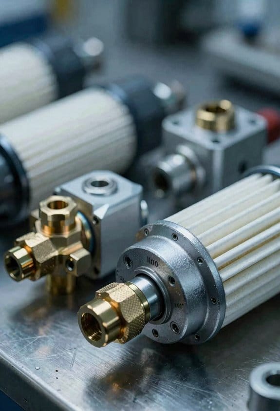
If you’ve ever walked into a paint booth and smelled oil, this is why filtration matters: oil and fine aerosols can ruin finishes and damage instruments. Use a high-efficiency coalescing filter when oil or liquid aerosols are present because it captures sub-micron droplets and protects valves and actuators; an example is a car-paint spray booth where a 0.01–0.3 micron coalescer prevents oily mist from clouding paint.
Before choosing filters, match flow capacity and pressure drop to your compressor so you don’t lose performance. Step 1: check your compressor’s maximum flow (SCFM) and operating pressure (PSI). Step 2: pick a filter rated equal to or greater than that SCFM and with a pressure drop under 2–3 psi at your operating flow. Step 3: verify element change intervals from the manufacturer.
If you’ve ever had dirty airline tools, here’s the practical particulate guidance: use depth particulate filters rated 5–40 microns depending on the application because they remove different sizes of debris; for example, a wood shop running pneumatic nailers should use a 5 micron filter on the tool air line. Use 5 micron for tool air such as grinders and nailers; use 40 micron for rough shop lines or sprinkler air where fines aren’t critical.
Think of odor and vapor filtration like a kitchen charcoal filter: activated carbon cartridges adsorb smells and oil vapors, so use them for painting booths and breathing air systems after particulate stages. Real-world example: a small auto-body shop stacks a 5 micron pre-filter, then an activated carbon cartridge rated for their SCFM to keep solvent odors out of the workspace.
Before you protect sensitive instruments, add a sub-micron final filter because instrumentation reacts to particles under one micron; for example, a lab’s pneumatic valve manifold should have a 0.01–0.3 micron final filter directly upstream. Steps to add it: 1) choose a filter with the micron rating needed, 2) confirm SCFM and pressure drop, 3) mount it as the last stage before the instrument.
If you want long life and predictable maintenance, follow this maintenance routine: 1) inspect bowls and elements weekly for visible oil or water, 2) replace particulate elements every 3–6 months or when differential pressure rises 10–15% above baseline, 3) replace coalescing and carbon cartridges per vendor hours or when performance drops. Example: a cabinet-maker logs filter pressure drop weekly and replaces the 5 micron element every 4 months, keeping nailer performance steady.
Use these concrete micron pairs as quick reference: 0.01–0.3 micron = coalescing/sub-micron for instruments and paint finish; 5 micron = tool air (grinders, nailers); 40 micron = rough shop lines and general moisture/debris removal. Match flow and pressure drop to your compressor and you’ll keep your tools, paint, and instruments working.
Maintenance & Replacement Rules to Prevent Downtime
Before you start maintenance, know why it matters: catching small issues early prevents unexpected downtime and big repair bills.
Here’s what to do each inspection cycle.
Why it matters: regular checks let you spot trends before they become failures.
Example: on my shop compressor, a slow ΔP rise over two months warned me of a clogged pre-filter before flow dropped.
Steps:
- Monthly visual check: inspect housings, sight glasses, bolts, and fittings for cracks, corrosion, or oil leaks; mark findings on your checklist.
- Quarterly element check: remove and inspect filter elements and regulator diaphragms; look for dark discoloration, oil globules, or hard crusts.
- Record pressures every inspection: log inlet and outlet pressures and ΔP on a simple spreadsheet or paper chart so you can see trends.
If you find elevated ΔP, act fast because pressure drop kills performance.
Example: last winter I saw ΔP jump from 3 psi to 12 psi in three weeks and replaced the element before downstream tools slowed.
Steps:
- Compare current ΔP to baseline; replace if it rises by 8–10 psi or reaches manufacturer limits.
- Replace filter elements every 6 months at minimum, or every 3 months in dusty environments — sooner if ΔP spikes.
- Swap elements immediately when you see visible contamination or moisture; don’t wait for the next scheduled check.
Before you test regulators, understand why stability matters: unstable regulators cause pressure creep and ruined parts downstream.
Example: a bakery’s regulator spring failed and slowly raised cooking pressures, burning batches until we replaced the kit.
Steps:
- Test regulator stability by applying a set pressure and watching for drift over 5 minutes.
- Replace springs or diaphragms if pressure shifts more than 2 psi during the test.
- Keep one spare regulator kit per regulator model on the shelf for same-day repair.
You should keep spares because downtime is costly and quick fixes work.
Why it matters: having parts ready turns hours of downtime into minutes.
Example: a production line stopped for a seized filter housing; a spare element and O-ring on hand got them back running in 18 minutes.
Steps:
- Stock at least one spare element and one regulator repair kit per critical unit.
- Store parts labeled with install dates and compatible model numbers.
- Replenish spares immediately after use.
Good records help you get better intervals over time.
Why it matters: data links failures to causes so you can shorten or lengthen intervals sensibly.
Example: after six months of logging, I found elements lasted 9 months on average in one area and 4 months in another, so I adjusted schedules.
Steps:
- Record date, ΔP, actions taken, and cause hypothesis for each failure.
- Review logs quarterly and update replacement intervals if median life shifts by more than 25%.
- Use a simple chart to visualize element life vs. environment so decisions are obvious.
Final practical checklist (use every visit):
- Visuals: housings, fittings, drains.
- Pressure log: inlet, outlet, ΔP.
- Element inspection: discoloration, moisture, odor.
- Regulator test: 5-minute stability check.
- Parts inventory: confirm spares on hand.
If you follow these steps, you’ll catch most problems early, replace parts at the right time, and keep your system running.
Calculating Cost Savings & ROI From Filters and Regulators
Here’s what actually happens when you improve your air quality and pressure control: your equipment runs smoother, uses less energy, and breaks down less.
Why it matters: you save real dollars on energy, parts, and downtime. For example, a small plastic molding shop I worked with cut compressor energy use by 12% after installing a regulator and upgraded filters, saving about $1,100 a month.
How I calculate lifecycle ROI (steps):
- Measure baseline numbers: record average monthly energy (kWh), number of valve/actuator failures per year, average downtime hours per failure, and current spend on parts and labor. Example: baseline = 15,000 kWh/month, 6 valve failures/year, 8 hours downtime/failure.
- Estimate improvements from filters/regulators: reduce energy use by X% (use vendor data or past installs), cut failures by Y%, and extend equipment life by Z years. Example assumptions: 12% energy reduction, 50% fewer failures, 3 extra service years.
- Convert improvements to dollars: multiply kWh saved by your electricity rate, multiply failure reductions by average repair cost and lost-production cost per downtime hour, and amortize extended life into annual savings. Example: 15,000 kWh × 12% = 1,800 kWh saved × $0.10/kWh = $180/month; 3 fewer failures × $2,000 per repair = $6,000/year.
- Add warranty benefits: if meeting filtration specs keeps warranty claims valid, estimate avoided replacement costs from at-risk claims. Example: avoiding a denied $25,000 drive replacement over 5 years = $5,000/year.
- Add all annual savings and divide by annualized cost of filters/regulators (purchase + installation + maintenance). That gives you ROI and payback period. Example: $180×12 + $6,000 + $5,000 = $7,160/year savings; if system costs $9,000 installed, payback ≈ 1.3 years.
What to track after install (steps):
- Monitor monthly kWh and compare to baseline.
- Log any failures and downtime minutes.
- Track filter replacement dates and regulator setpoint stability.
Example: track kWh on your utility bill, record failures in a simple spreadsheet, and check regulator pressure weekly for the first 90 days.
A quick-payback check you can do today:
- Estimate monthly energy savings = baseline kWh × expected % reduction × your $/kWh.
- Estimate annual maintenance/repair savings = (baseline failures × expected % reduction) × cost per repair.
- Add any warranty-avoidance dollar amount.
- Divide your installed cost by annual savings to get years to payback.
Short example: $9,000 cost ÷ $7,160 annual savings = 1.3 years.
Practical tips:
- Use measured data whenever possible; don’t rely only on vendor claims.
- If you expect less than 2-year payback, buy it. Simple.
- Keep replacement filters on a calendar so you don’t void warranties.
If you want, send me your baseline numbers (kWh, failures/year, repair cost, installed cost) and I’ll run the numbers for you.
Quick Troubleshooting: Signs of Bad Filters or Failing Regulators
If you’ve ever had a tool quit mid-job, this is why.
Spotting early signs of a bad filter or a failing regulator matters because catching problems quickly prevents downtime and costly repairs. For example, on a tire shop floor a compressor that cycles fast can ruin a wheel torque gun mid-torque and cost you an hour of work.
1) What does pressure fluctuation tell you?
Why it matters: unstable pressure can damage tools and give you inconsistent results.
How to check:
- Watch the gauge at the tool while operating. If the needle jumps more than 5–10 psi during a steady cut or blow-off, you have a problem.
- Measure at the regulator outlet and the tool inlet to pinpoint where the drop happens.
Example: when you’re spray-painting a car panel and the spray pattern thins every few seconds, the regulator is likely failing.
2) How to interpret unusual compressor cycling
Why it matters: short cycling wastes energy and wears the compressor motor prematurely.
How to check:
- Count cycles: if the compressor runs more than 6 starts per hour for a small shop unit, that’s excessive.
- Inspect for clogged intake or a stuck unloader valve which can mimic regulator issues.
Example: in a small garage, the compressor kicking on every 5 minutes while no tools run usually means a leak or bad regulator.
3) What to look for in filter elements
Why it matters: dirty filters reduce airflow and raise pressure drop, so tools starve for air.
How to check:
- Pull filter elements and look: dark, oily, or wet media means replace the element.
- Measure ΔP (inlet vs. outlet) with a gauge — replace the element if ΔP exceeds the manufacturer’s spec (often 5–10 psi).
Example: a shop secretary notices air hammers losing power; you open the filter bowl and find a black, greasy element.
4) Why actuators jerk or move inconsistently
Why it matters: jerky motion damages valves and can ruin the part you’re working on.
How to check:
- Listen and watch a cylinder under load. If motion stalls or stutters, test air downstream of the regulator for water or oil contamination.
- Blow out the line and replace the filter/dryer if you see moisture.
Example: an automated press that drops unevenly due to a sticky valve shows brown sludge in the downstream tubing.
5) How to spot oil or particulate downstream
Why it matters: oil and dirt foul valves, seals, and sensors, shortening their life.
How to check:
- Visually inspect clear tubing or use a paper towel at a bleed point to catch oil/particles.
- If you find oil, add or service an aftercooler and coalescing filter.
Example: a paint booth operator finds brown specks on finished panels and traces them to a torn filter element.
6) How to test regulator response
Why it matters: slow recovery means the regulator can’t maintain set pressure under load.
How to check:
- Set the regulator to a known pressure (e.g., 90 psi).
- Open a tool or bleed a line to drop pressure by 15–20 psi.
- Time how long it takes to return to 90 psi; under 5 seconds is typical for many systems.
Example: on a sandblaster, if pressure takes 15 seconds to recover, final piece finish will be inconsistent.
What to do when you find a suspect part
Why it matters: delaying replacement risks bigger failures and higher costs.
Steps:
- Replace the filter element or cartridge immediately if it’s dark, wet, or ΔP is too high.
- If the regulator won’t hold pressure or recovers slowly, replace the regulator cartridge or the whole regulator.
- After replacing parts, run the system under normal load and verify pressure stability within ±5 psi.
Example: swapping a clogged coalescing element in a collision shop restored steady spray patterns within 10 minutes.
Quick checklist before you leave:
- Gauge drift >5–10 psi? Check regulator.
- ΔP over spec or dark element? Replace filter.
- Oil or particles downstream? Add/service aftercooler and coalescer.
- Actuator jerking? Check for moisture and replace filter/dryer.
Replace suspect elements or the regulator promptly to avoid equipment damage and keep your work consistent.
Frequently Asked Questions
Can Regulators Cause Measurement Errors in Downstream Sensors?
Yes — I’ve seen regulators cause sensor drift and pressure hysteresis downstream; if they oscillate, leak, or creep they alter readings over time, so you’ll want stable, well-maintained regulators and proper filtration to prevent errors.
Are There Regulations for Filter Disposal and Contaminated Condensate?
Yes — though it’s tedious, you can’t ignore it: I follow local waste tracking rules and hazardous classification guidance for contaminated condensate and spent filters, ensuring proper disposal, documentation, and licensed contractor handling to avoid fines.
Can Water-Cooled Compressors Eliminate Need for Downstream Filters?
No — I don’t think water-cooled compressors eliminate downstream filters; they reduce water contamination by improving heat rejection, but you still need filtration to remove condensate, oil, particulates and protect valves, tools, and instruments.
Do Regulators Affect Pneumatic Safety Interlocks or Emergency Systems?
About 10% energy loss paints the risk: I’ll tell you yes—regulators impact control reliability and interlock response by altering pressure timing; unstable regulation can delay or false-trigger safety interlocks, compromising emergency system performance.
How Do Altitude and Ambient Temperature Change Regulator Performance?
Altitude derating reduces available regulator outlet pressure at higher elevations, and temperature drift shifts setpoints with ambient changes. I’ll compensate by adjusting settings, choosing altitude-rated regulators, and compensating for temperature when calibrating and maintaining units.