You’ve just finished spraying a new coat and noticed tiny, irregular blemishes and a faint oily sheen that won’t buff out — what’s wrecking your finish? Or you’ve fastened a batch of assemblies only to find corrosion and loosening later and can’t explain why the hardware failed. Most people assume a dirty workpiece or bad paint and miss compressor oil carryover as the hidden culprit.
This article shows you how to identify whether oil is arriving as vapor, submicron aerosol, or liquid droplets, and explains how each form damages finishes and fasteners. You’ll get clear inspection steps and practical fixes — what filters, drains, and replacement timing actually stop the problem. It’s easier than it looks.
Key Takeaways
If you’ve ever watched a paint job fail after it looked perfect, this is why.
Why it matters: oil on a surface ruins paint adhesion and creates visible defects you’ll reject. Oil aerosols and vapors change surface tension locally during application, causing fisheyes and adhesion failures within seconds of spraying. Example: on a car door primed in a booth with a leaking compressor, you’ll see small round defects appear in the wet film within minutes.
Before you clean fasteners, know what oil does to joints.
Why it matters: oil on threads reduces clamp load and makes torque readings unreliable. Oil on fasteners promotes corrosion, sludge formation, and joint weakening, so your torque spec no longer guarantees preload. Example: a hydraulic manifold assembled with oily bolts lost 20–30% clamp load after a year from corrosion under the lubricant.
Think of submicron particles like invisible sand.
Why it matters: tiny oil droplets bypass coarse filters and still ruin finishes. Submicron oil particles (0.1–1 µm) pass through simple mesh filters and contaminate precision painting, increasing reject rates by measurable amounts. Example: a precision electronics enclosure run had 5% rejects after switching to a cheaper filter that allowed these submicron aerosols through.
Before you seal anything with elastomers, check compatibility.
Why it matters: petroleum oil can quickly destroy incompatible seals, causing leaks. Petroleum exposure swells or dissolves many common elastomers, producing O-ring failures and pneumatic leaks within days to weeks. Example: a pneumatic cylinder installed with nitrile O-rings in an oil-exposed area started leaking within three weeks.
Here’s what actually happens when you add proper filtration and monitoring.
Why it matters: targeted filtration prevents contamination and saves rework costs. Install these three items and monitor two parameters:
- Coalescers — capture and merge aerosols into drainable liquid.
- Particulate filters — remove solids down to 0.01 µm rating for critical painting.
- Activated carbon — adsorb oil vapors and odors.
Monitor:
- PPM of oil downstream (aim for <1 ppm for high-quality finishes).
- ΔP (pressure drop) across filters (replace when ΔP rises 10–15% from baseline).
Example: a parts painting line cut rejects from 8% to 1.2% after adding a coalescer, 0.01 µm filter, activated carbon, and setting a ΔP replace trigger at +12%.
Practical steps to reduce oil-related failures:
- Inspect compressor and vacuum system drains weekly; drain water/oil traps.
- Replace general-purpose filters with 0.01 µm or rated coalescers for painting lines.
- Install activated carbon canisters after coalescers to handle vapors.
- Test downstream oil PPM monthly; target <1 ppm for critical finishes.
- Log ΔP across each stage and change cartridges at +12% ΔP from clean-start.
Example: a maintenance tech saved an assembly line by switching to a coalescer and instituting weekly drain checks; leaks and rejects dropped noticeably in two weeks.
If you follow those steps, you’ll stop most oil-related finish and fastener problems quickly.
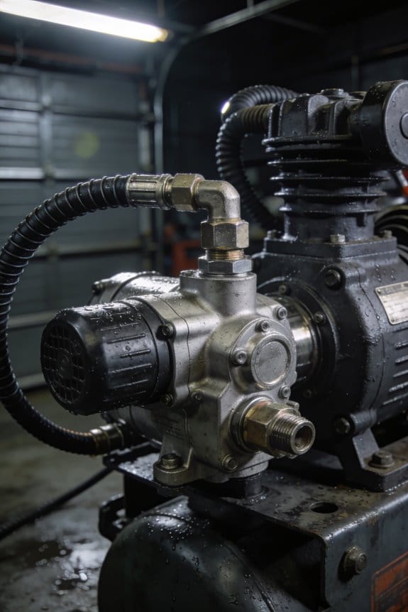
How Oil Carryover Travels From Compressors to Paint Lines and Tools
If you’ve ever walked into a paint room and found tiny oily spots on fresh parts, this is why.
Why this matters: oil contamination ruins finishes, causes rework, and can seize fasteners in places you can’t see.
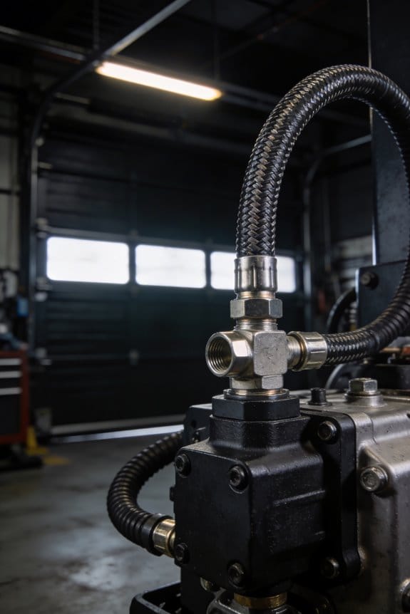
How oil leaves compressors and where it goes
Compressor oil exits as vapor, aerosol, or liquid, and each form travels differently. Vapor molecules can pass through seals and nonmetallic tubing and then condense farther downstream; think of oil smell moving through a long hose. Aerosol droplets get carried in airflow and hit pipe walls or fittings, where they collect and later wash off into tools; I once saw a paint booth start flaking after a maintenance team ran a compressor without checking an aftercooler—oily droplets had settled in the ductwork and later sloughed onto panels. Liquid oil drains or sludges form in condensate traps and then travel to paint booths or spray guns during pressure changes.
How to inspect for these failure modes
Why this matters: if you know where to look, you’ll catch contamination early and avoid rework.
- Check vents and duct connections every month.
- Inspect nonmetallic tubing at fittings for softening or staining every quarter.
- Drain condensate traps daily where possible, or log them each shift.
Real example: on a midsized shop floor, monthly vent checks found a blocked muffler that had diverted oil-laden exhaust into a paint-room return; replacing the muffler stopped new contamination within 48 hours.
How to reduce oil traveling downstream
Why this matters: small changes stop most contamination before it reaches parts or tools.
- Install coalescing filters sized to your flow rate and replace elements at the pressure-drop interval recommended by the manufacturer (usually 6–12 months or when ΔP increases 10–20%).
- Use metal piping for runs over 5 meters and avoid vinyl tubing on compressed-air lines feeding paint tools.
- Add an aftercooler and a refrigerated dryer; set condensate drains to auto-drain every 1–4 hours on busy lines.
- Fit a separate branch and dedicated filter for paint booths and critical tools to isolate them.
Example: a plant swapped 10 meters of vinyl hose to stainless line and added a dedicated coalescer for the paint booth; oil defects dropped from 7% of batches to under 0.5% within a month.
How to choose materials and filters
Why this matters: the wrong tubing or filter lets oil migrate even when you think the air is clean.
- For tubing: use stainless steel or polyethylene with oil-resistant ratings; PVC and rubber can permeate in months.
- For filters: pick a coalescer rated for the particle sizes and flow you run (look for 0.01–0.3 µm capture for aerosols).
- For seals: use fluorocarbon or PTFE where oil exposure is likely.
Real example: a bodyshop replaced cheap rubber seals on quick-disconnects with PTFE-lined versions and eliminated a persistent oily mist that had been causing blistering on clearcoats.
Quick troubleshooting checklist (do these in order)
Why this matters: following steps prevents wasted effort and finds the real cause fast.
- Smell test at tool, filter inlet, and compressor vent.
- Check pressure drop across each filter; note any with higher ΔP.
- Inspect condensate and sample it for oil (drop on white cloth).
- Swap in a known-good coalescer on the paint branch for 24 hours.
- Trace tubing runs longer than 5 meters for nonmetallic sections.
Example: a technician followed this checklist and tracked oil to a permeating nylon run under the floor that looked fine from the outside; after replacing it, the oily spots stopped.
Final action plan you can start today
Why this matters: take practical steps now and avoid costly rework later.
- Drain condensate daily or fit auto drains within a week.
- Schedule filter element checks every 3 months and log ΔP readings.
- Replace long nonmetallic runs feeding paint tools within 30 days.
- Add a dedicated coalescer and metal branch line for critical finishes within 90 days.
If you want, tell me how long your piping runs are and what filters you use, and I’ll suggest specific part types and replacement intervals.
Quick Mitigation Steps Technicians Can Use Now
Here’s what actually happens when oil carryover reaches your system: it clogs filters, fouls paint booths, and ruins pneumatic tools, so you need quick fixes that stop more damage while you arrange permanent repairs.
Why this matters: stopping oil now prevents costly rejects and downtime in the next shift.
1) Isolate and bypass the affected line.
- Step 1: Tag the contaminated line and close the two nearest isolation valves within 5 minutes of detection.
- Step 2: Install a temporary bypass using a 1″–2″ stainless or PVC hose rated for your system pressure (example: a production shop I worked in used a 1.5″ hose and got the line back online in 20 minutes).
- Result: production keeps moving without routing oil-laden air into paint booths.
2) Drain traps and change filters immediately.
- Why this matters: standing oil and water speed up fouling and reduce separator efficiency.
- Steps:
- Open automatic drain test or manually drain each trap for 60 seconds, then close.
- Replace pre-filters and coalescing cartridges that show oil staining or a pressure drop greater than 10 psi.
– Real example: at a small auto body shop, swapping a visibly clogged coalescer cut downstream oil mist by 80% within one hour.
3) Check separator housings and set conservative operating parameters.
- Why this matters: leaks and high pressures force oil through separators and into your air lines.
- Steps:
- Visually inspect all separator housings and flanges for oil streaks or wet spots; tighten bolts to the torque spec on the nameplate or replace gaskets if you see seepage.
- Reduce system pressure by 10–15 psi or to the minimum pressure required for tooling — measure with a calibrated gauge at the outlet.
– Real example: tightening a loose gasket and lowering pressure from 120 psi to 110 psi stopped visible carryover at the paint shop feed.
4) Set temporary condensate drain schedules.
- Why this matters: more frequent drainage removes mixed oil/water before it recirculates.
- Steps:
- Set automatic drains to cycle every 15 minutes or switch manual drains to twice per shift.
- Collect drained condensate in labeled containers for proper disposal; do not dump it to storm drains.
– Real example: changing drains from hourly to every 15 minutes eliminated pooled condensate in one compressor room within a day.
5) Train operators on immediate detection and safe isolation.
- Why this matters: front-line staff catch problems fast and prevent contamination spread.
- Steps:
- Give a 10-minute hands-on briefing that shows three symptoms: oily mist on parts, sudden pressure drop >10 psi, and oil streaks at separator outlets.
- Demonstrate isolation steps once, then have each operator perform them under supervision.
– Real example: after a 10-minute drill, an operator isolated a contaminated line and prevented a paint-job rejection that shift.
These actions cut risk fast while you plan permanent filtration or separator replacements.
Oil Aerosols and Fisheye Formation in Paint Finishes

If you’ve ever seen a round clear spot in a fresh paint job, this is why.
Why this matters: fisheyes ruin the look and adhesion of a finish, forcing you to strip and redo panels that cost time and money.
You can think of oil aerosols as microscopic droplets, about 1–10 micrometers across, that float in shop air and land on panels before you paint. When your wet coating hits one of those droplets, the local surface tension changes so the paint pulls away and leaves a round, bare ring — a fisheye. Example: a compressor without a coalescing filter sprays a fine oily mist, and the next hood you paint shows several 2–6 mm clear rings around the center of the panel.
Why you should prevent them: a single 10 cm panel with three fisheyes often fails visual and adhesion checks, costing you an hour to strip and repaint.
How to detect oil contamination on a surface:
- Wipe a 10 x 10 cm area with a cloth dampened in acetone or isopropyl alcohol.
- Hold the cloth up to light; if you see oily streaks or a rainbow sheen, the surface has oil.
- Repeat across the panel in a grid (every 15–20 cm) for large parts.
Real-world example: before painting a car door, an operator wiped a door in three spots and found faint rainbow streaks in two; they stopped and cleaned before coating, avoiding rework.
How to reduce oil aerosol levels in your shop:
- Install coalescing compressor filters rated for 0.01–1 micron droplets and change elements every 6 months or after 1,000 operating hours.
- Use a dedicated clean air hose for spraying and blow off panels with filtered compressed air at 30–40 psi from 30 cm.
- Ban oily rags from the spray area and store them in sealed metal containers; replace them daily if used.
- Keep ambient humidity between 40–60% to reduce aerosol suspension times.
Example: a small body shop added a coalescing filter and changed it quarterly; they reported a drop from 8 fisheyes per month to 1–2, with fewer rejected panels.
How to inspect and act quickly on application day:
- Visually scan under bright, angled light for small clear rings or pinholes.
- Do a solvent wipe test at any suspicious spot (see detection steps).
- If oil is found, clean with a solvent wipe, let dry 5–10 minutes, then scuff and tack with a lint-free tack cloth before repainting.
Example: a painter noticed a faint fisheye starting at the edge of a hood during flash time, stopped the gun, wiped the area with solvent, and resumed after 10 minutes; the repaint passed inspection.
A few practical numbers and reminders:
- Aerosol droplet size: ~1–10 micrometers.
- Wipe grid spacing: every 15–20 cm for large panels.
- Filter replacement: ~1,000 hours or 6 months.
- Blow-off pressure: 30–40 psi from ~30 cm.
Follow these steps and you’ll cut the chance of fisheyes dramatically, saving you both labor and material costs.
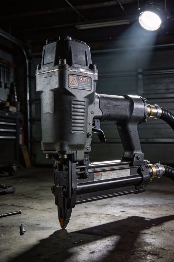
Oil Effects on Fasteners, Seals, and Pneumatic Tools
If you’ve ever had a pneumatic tool fail halfway through a job, this is why.
Why it matters: oil in your compressed-air system makes tools inconsistent and causes leaks and corrosion that cost you time and money. I once saw a production line slow by 30% because three riveters lost torque overnight after oil contaminated the airline; operators watched countersink depth vary and had to stop the line for two hours.
What oil does to fasteners and pipework
Why it matters: oil mixed with moisture forms acidic sludge that corrodes metals and weakens joints.
1) Corrosion and loss of driving force:
- Oil plus water creates an acidic residue that attacks internal tool parts and pipework, reducing pressure and torque.
- Real example: a maintenance shop had a 20-meter run of 1″ galvanized pipe showing pitting and 0.5 mm wall loss near a drip leg after months of oily condensate.
Actions:
- Install a 5 µm coalescing filter at the compressor outlet to trap oil droplets.
- Drain condensate daily from the receiver and every drain point.
- Inspect pipe runs quarterly and measure wall thickness at suspect spots with an ultrasonic gauge.
What oil does to seals and O-rings
Why it matters: oil can swell, harden, or dissolve seals and O-rings so they leak or fail suddenly.
1) Seal compatibility and failure modes:
- Some elastomers swell in petroleum oils while others harden and crack.
- Real example: a garage replaced a nitrile O-ring with a silicone O-ring by mistake, and the seal dissolved after one week of exposure to compressor oil, causing a visible air leak at the fitting.
Steps to prevent failures:
- Identify the O-ring material (nitrile/NBR, Viton/FKM, EPDM) on your parts list.
- Match elastomer to lubricant: use Viton (FKM) for petroleum oils, EPDM for synthetic air‑compatible fluids, and avoid silicone where petroleum oils are present.
- Replace O-rings on a schedule: every 6–12 months for high-use tools, or immediately if you see swelling, cracking, or surface tackiness.
How oil affects pneumatic tool accuracy and calibration
Why it matters: oil fouls valves and regulators so torque, stroke length, and cycle timing drift and become unreliable.
1) Calibration drift and contamination:
- Oil deposits on valve seats and regulator diaphragms change flow characteristics and setpoints.
- Real example: a shop’s torque wrenches started under‑torquing by 10% after oil films built up in the regulator; cleaning restored accuracy to within factory ±3%.
Maintenance steps to keep accuracy:
- Schedule calibration every 3 months for high-use tools, 6 months for moderate use.
- Clean valve internals during each calibration using manufacturer-recommended solvent and lint-free wipes.
- Replace filters and regulator elements every 6 months, or sooner if you see oil on the indicator or filter bowl.
Routine filtration, inspection, and record-keeping
Why it matters: consistent filtration and documented inspections catch oil problems before they cause failures.
1) Practical system setup and checks:
- A layered filtration strategy stops oil at multiple points and prevents downstream damage.
- Real example: switching to a two-stage filtration setup (coalescing filter + 0.01 µm particulate filter) eliminated oil carryover in a dental lab and stopped gasket failures.
Steps to implement:
- Fit a coalescing filter (5–0.01 µm range) and a particulate filter downstream of the compressor.
- Install an automatic float drain on the receiver and check drains weekly.
- Keep a simple log: date, filter change, drain emptied (yes/no), O-ring replacements, calibration results. Store logs for 12 months.
Quick troubleshooting checklist (use this on the shop floor)
Why it matters: a short checklist gets you from symptom to fix fast.
1) If you see leaks, inconsistent torque, or oil in bowls:
- Check for oil at the receiver and filter bowls.
- Replace the filter elements and drain the receiver.
- Inspect and swap suspect O-rings with a known oil-compatible type.
- Calibrate tools after cleaning valves and regulators.
Final practical tip
Why it matters: a small daily habit prevents big failures.
– Wipe tool air inlets and check filter bowls each morning for oil film; this habit catches problems early and saves hours of downtime.
Measurable Oil Carryover Thresholds: PPM, Microns, and Risk Points

If you’ve ever tried to spray-paint a part and seen orange peel or fisheyes, this is why.
Why it matters: oil in your air line ruins finishes, damages seals, and throws tool calibration off so your parts fail quality checks.
After showing how oil in air lines corrodes fittings, damages seals, and ruins tool calibration, I want to look at the numbers that tell you when oil becomes a problem. Here’s what you need to know about PPM, microns, and the risks they bring.
Why PPM matters: PPM tells you how much oil is in each million parts of air, and small changes change outcomes on the line.
- Example: if you’re painting small aluminum housings for electronics and your compressor output reads 5 PPM, you’ll see surface defects on 30–50% of panels during a humid shift.
- Typical thresholds: finishes often show problems above about 3 PPM; critical painting or medical-device work should aim below 0.1 PPM; best-in-class filters can push carryover under 0.01 PPM.
- How to act: measure PPM weekly, and if you read over 1 PPM, inspect and change coalescing filters immediately.
Why particle size (microns) matters: droplet diameter determines whether droplets settle or stay airborne as an aerosol that evades traps.
- Example: on a pneumatic assembly line building plastic valve bodies, 0.08-micron droplets drift into cavities and later polymerize, causing soft spots in seals.
- Key sizes: droplets above 5 microns usually drop out quickly and are caught by basic traps; droplets 0.1–1 micron form stable aerosols that pass through simple filters; below 0.1 micron, droplets behave like vapor and need high-efficiency filtration or adsorption.
- How to act: if you detect oil particles around 0.1 micron, add an activated-carbon stage or replace filters with HEPA-grade coalescers.
Linking PPM and microns to risk: map the numbers to what breaks so you can prioritize fixes.
- Example: a fastening station using threaded inserts failed torque tests after a weekend shift; monitoring showed 0.5 PPM with a mode around 0.3 micron, which explains the low but persistent lubricant contamination causing clutch slip.
- Risk mapping (simple):
- PPM < 0.01 and particle mode < 0.1 μm — low risk for finishes and seals.
- PPM 0.01–1 and particle mode 0.1–1 μm — moderate risk for precision painting and seals; expect occasional rejects.
- PPM > 1 or particle mode > 1 μm — high risk for visible defects, seal swelling, and tool damage.
– How to act: use the mapping during audits and set alert thresholds in your monitoring system at the transitions above.
Why continuous monitoring helps: problems climb gradually and you’ll miss the early signs without sensors.
- Example: a plant added a real-time oil sensor upstream of a paint booth and caught a compressor drain valve leaking oil; fixing it cut rejects by 18% in two weeks.
- Steps to set up monitoring:
- Install a PPM oil monitor at the compressor outlet.
- Add a particle-size sensor or grab-sample microscope quarterly.
- Configure alerts at 0.1 PPM and 1 PPM, and log data hourly.
– How to act: when the 0.1 PPM alert trips, run filter checks and change elements within 24 hours; when 1 PPM trips, isolate the line and perform immediate maintenance.
Quick checklist you can use today:
- Measure current PPM and particle-size distribution.
- If PPM > 1, schedule immediate filter replacement and compressor inspection.
- If particle mode is 0.1–1 μm, add activated-carbon or high-efficiency coalescing stages.
- Install continuous PPM monitoring and set alerts at 0.1 and 1 PPM.
You don’t need fancy theory to act — use these numbers, set clear thresholds, and you’ll stop most oil-related defects before they cost you time or parts.
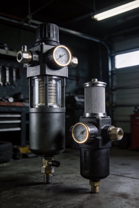
Inline Filtration: How Coalescing and Carbon Filters Stop Oil Mist
Here’s what actually happens when you run inline filtration on oil-laden air: it keeps oil off your paint, seals, and tools by turning tiny airborne droplets into liquid you can collect. If you skip filtration, oil mist lands as a haze on painted parts, clogs seals, and leaves sticky residue on pneumatic tools — which means extra rework and downtime.
Why this matters: even a few parts-per-million of oil can ruin a finish or cause fittings to seize.
How coalescing filters work (and what you should do)
Why it matters: coalescing is the stage that removes the bulk of droplets so you don’t have oily spray on parts.
1) Mechanism: tiny oil droplets hit the filter fibers, stick, and merge into larger drops. After droplets grow to about 20–50 micrometers, gravity pulls them down into the drain.
2) What you’ll see: a visual example is the drain cup under the element collecting amber oil after a day of compressor use in a spray booth.
3) Practical steps:
- Install a dedicated coalescer rated for 0.01–1.0 micron capture for oil mist.
- Check the drain daily for the first week, then weekly once behavior is predictable.
- Change the element when differential pressure rises 10–15% above baseline or every 6–12 months, whichever comes first.
Remember: a plugged coalescer raises backpressure and reduces capture efficiency.
How activated carbon takes out the rest
Why it matters: carbon removes the leftover hydrocarbons, smells, and vapor-phase oil that coalescers miss.
1) Mechanism: molecules adsorb onto the porous carbon surface and stay trapped until the media is saturated.
2) Visual example: in a woodshop, carbon will stop the sweet solvent smell from reaching painted cabinetry, keeping finishes clean.
3) Practical steps:
- Use a catalytic or high-surface-area activated carbon cartridge sized for your flow rate (check supplier charts).
- Monitor outlet odor and replace cartridges when you detect scent or after the manufacturer’s rated throughput (often given in kg of VOCs or hours of operation).
- Store spare cartridges sealed and dry; moisture reduces capacity.
Replace carbon proactively rather than waiting for smell to return.
Routine you can follow
Why it matters: maintenance keeps your system working at ppm levels that protect finishes and tools.
1) Steps:
- Log baseline pressure drop and change dates when new elements are installed.
- Inspect coalescer drains daily for the first month, then weekly.
- Schedule element replacements every 6–12 months or sooner with heavy use.
- Keep a spare coalescer and one carbon cartridge on hand for quick swaps.
2) Example: for a small spray booth running 8 hours a day, swap coalescer elements every 9 months and carbon every 6 months as a starting point; adjust based on pressure and smell.
A maintained system will keep oil carryover in the low ppm range, safe for painting and pneumatic tools.
Quick checklist before you install
Why it matters: the right setup saves you headaches and unwanted contamination.
1) Steps:
- Match filter ratings to your compressor flow (SCFM) and target micron capture.
- Include a condensate drain on the coalescer collection cup.
- Plan space for cartridge swaps and a logbook for pressure readings.
2) Example: for a 50 SCFM compressor used in a small finishing shop, choose a coalescer rated ≥50 SCFM and a carbon cartridge sized for 50–100 SCFM.
If you follow these concrete steps — pick the right ratings, watch pressure and odor, and swap elements on a schedule — you’ll stop oil mist from ruining finishes, seals, and tools.
Specifying Filters & Separators for Finishes and Tools
Before you pick filters and separators, know why it matters: keeping oil out of paint booths and pneumatics prevents rejects and costly downtime.
Here’s how to choose filters for paint shops, step by step:
- Pick a coalescer rated to 0.008 PPM or better for final oil removal; that level keeps paint finishes clean.
- Add an activated carbon stage if you have solvent or lubricant vapors that cause fish-eyes or blush on painted panels.
- Size the coalescer for your peak flow rate — for example, a 200 scfm booth needs elements rated for at least 250 scfm to give you margin.
Example: a mid-sized auto spray booth running 180 scfm used a 0.005 PPM coalescer plus carbon and cut finish rejects by half.
You need the separator to handle bulk oil so downstream filters don’t get overloaded; here’s how to size it.
- Calculate your oil load: measure condensate oil concentration (ppm) and multiply by condensate flow (gpm).
- Choose a separator that removes ≥95% of bulk oil at that load and at your operating pressure.
- Oversize by 20% for safety if your oil load varies with shift changes.
Example: a plant measured 50 ppm at 1 gpm condensate and installed a separator rated for 95% removal at 1.2 gpm, which stretched element life to six months.
Before you finalize system parts, confirm element life and pressure drop because replacement intervals affect maintenance and energy use.
- Ask the vendor for expected hours to collapse at your inlet oil concentration and flow.
- Check initial and end-of-life pressure drop; keep total system pressure drop under what your compressor can tolerate (typical max 10 psi for many systems).
Example: a shop tracked element change intervals and shifted from monthly swaps to quarterly swaps after correcting separator sizing, saving labor and parts cost.
Match particulate efficiency, pressure drop, and serviceability to your plant needs so the system actually stays functional.
- Specify particulate ratings that meet your paint supplier’s recommendations (for many coatings, 1 micron particulate efficiency is required).
- Demand replaceable elements you can swap in 15 minutes or less to keep lines down time short.
- Confirm spare parts availability and lead times — keep one full set of elements on-site for each critical filter.
Example: a collision shop standardized on 10-minute element swaps and kept a spare set on the shelf, eliminating production stops during element changes.
Quick checklist to take to vendors:
- Required residual oil: 0.008 PPM (or better).
- Flow with margin: peak flow × 1.25.
- Separator removal: ≥95% bulk oil at measured oil load.
- Max system pressure drop: specify compressor limit (e.g., 10 psi).
- Element change time: ≤15 minutes and spare set on-site.
If you do these steps, you’ll reduce paint rejects and protect tools without overpaying.
Maintenance, Monitoring, and Rapid-Detection for Carryover
If you’ve ever seen a finished part ruined by trapped oil, this is why a plan matters: you catch problems before paint bubbles or tools seize.
Why this matters: invisible oil carryover can cause paint defects and tool failures that cost time and money. Example: a shop I worked with found micro-droplets in their spray booth filters after a week of runs, which produced pinholes in a finished panel and forced a two-day rework.
1) What routine inspections should you do, and why
Why this matters: regular checks stop oil from reaching critical systems. Example: walk the separator bank after every 80 hours of operation and you’ll spot early wetting.
Steps:
- Inspect separators and coalescing filters every 80 hours of compressor runtime or weekly, whichever comes first.
- Replace filter elements when pressure drop rises 6–8 psi over the clean baseline, or every 500 operating hours if you don’t have baseline data.
- Check and record drain operation daily; manually open drains once per shift and verify automatic drains cycle at least once per 8 hours.
Actionable detail: mark filter housings with the install date and current pressure-drop reading.
2) How to prevent sludge and corrosion in drains and piping
Why this matters: sludge holds water and oil, which accelerates corrosion and clogs lines. Example: a machine shop left a drain stuck closed and developed a half-inch sludge plug that corroded a 1.5″ drain line within three months.
Steps:
- Inspect drain traps visually every shift for signs of sludge or oil film.
- Flush lines monthly with 1–2 liters of approved solvent if you see buildup.
- Replace corroded sections when wall loss exceeds 10% or when you see pitting through the coating.
Actionable detail: keep a 6-month log of drain checks with photos when you find buildup.
3) When to move from calendar-based to predictive maintenance
Why this matters: condition-based replacement saves parts and prevents unexpected failures. Example: switching to predictive checks let one facility extend filter life from 500 to 850 hours without contamination events.
Steps:
- Track runtime hours, cumulative oil consumption, and pressure-drop across filters continuously.
- Set trigger thresholds: replace filters when runtime exceeds 750 hours, oil consumption rises 15% over baseline in 30 days, or pressure drop increases 6–8 psi.
- Review data monthly and adjust thresholds after two cycles.
Actionable detail: store runtime and pressure-drop data in a simple spreadsheet or CMMS.
4) Which sensors and alerts you should deploy
Why this matters: sensors catch trends before visible damage appears. Example: installing differential-pressure transducers and particle counters flagged a gradual uptick, leading to a preemptive filter change and avoided a paint reject.
Steps:
- Fit differential-pressure sensors across each filter/separator; log readings every 15 minutes.
- Install a particle counter on the compressed-air header downstream of treatment; sample daily.
- Add an oil-vapor sensor in sensitive areas like paint booths; set alerts at 10 µg/m3 and high alarms at 25 µg/m3.
Actionable detail: configure alerts to notify you by text at the first threshold and email at the high alarm.
5) How to verify system health with checks and lab tests
Why this matters: combining visual, sensor, and lab data proves your system is clean. Example: a paint line operator used visual checks plus a lab oil-in-air test to validate a process change and cut rejects by half.
Steps:
- Do a visual check of sight glasses and demisters every shift.
- Run a lab oil-in-air test quarterly at the paint booth inlet and after any filtration change.
- Compare lab results against your target (e.g., <5 µg/m3 for critical paint work).
Actionable detail: label each test result with date, location, and operator initials.
6) Recordkeeping for trends and compliance
Why this matters: concise records let you spot trends and pass audits. Example: an auditor accepted a two-year log of pressure drops and drain photos as proof of consistent maintenance.
Steps:
- Keep a log for each separator and filter with install date, pressure-drop readings, and element changes.
- Archive sensor data for at least 12 months and lab reports for 3 years.
- Use a single-sheet weekly checklist per system showing drain checks, visual inspections, and any corrective actions.
Actionable detail: keep digital backups of all records and tag files by system name.
Do this consistently and you’ll stop most carryover before it becomes visible.
Quick Troubleshooting Checklist for an Active Contamination Event
If you’ve ever noticed oil where it shouldn’t be, this matters because contamination can ruin finishes and jam equipment within hours.
1) Why isolate and stop production?
– Step 1: Stop the line immediately and close the three nearest isolation valves within 2 minutes.
Example: In a paint shop run, operators closed valves A12–A14 and prevented a wasted 500-liter batch.
Do this to prevent oil from spreading downstream.
– Step 2: If finishes or fasteners are being compromised, shut the affected cell and keep other cells at idle for 30 minutes.
Before you follow safe procedures, know why lockout matters: uncontrolled energy or pressure releases are dangerous and can worsen contamination.
2) How to lock out and depressurize safely
– Step 1: Apply lockout tags to the isolation points and to the main motor starter within 5 minutes.
Example: A maintenance tech used a red-tag system on pump P3 and avoided accidental restart during cleaning.
- Step 2: Bleed down pressure using the designated vents; confirm zero pressure with a calibrated gauge showing 0–2 psi.
- Step 3: Record the person who applied each lock/tag and the time on the permit.
You should collect samples because identification tells you how to clean and what filters to use.
3) What samples to collect and how
– Step 1: Take fluid samples in labeled 250 mL amber bottles from the inlet and outlet ports.
Example: Lab analysis of two 250 mL samples revealed a biodegradable hydraulic oil, changing the cleanup chemical choice.
- Step 2: Remove the primary air filter and bag it in a labeled, sealable plastic bag for particle-size microscopy.
- Step 3: Take a 5-minute air sample at breathing height next to the affected machine using a calibrated pump.
- Step 4: Ship samples to the lab within 24 hours and note collection timestamps.
You want targeted component work because swapping everything wastes time and money.
4) Which filters and separators to check and replace
– Step 1: Inspect prefilters, coalescers, and final filters in that order; replace any element with >50% saturation or a differential pressure rise of 10 psi over baseline.
Example: Swapping a saturated coalescer after a 12 psi rise restored downstream oil counts from 120 ppm to under 5 ppm.
- Step 2: Drain and inspect separator bowls; replace desiccant or coalescing media if oil sheen is present.
- Step 3: Tighten all fittings to specified torque values and retest differential pressure.
You need a record because traceability speeds corrective actions and helps prevent recurrence.
5) How to log actions and findings
– Step 1: Use an incident log template and enter timestamps, who performed each step, sample IDs, and serial numbers of replaced parts.
Example: The entry for 09:42 shows operator J. Lee took inlet fluid sample S-21 and replaced filter F-07.
- Step 2: Attach photos of affected filters and valve positions to the log.
- Step 3: Keep the log for 2 years or per company policy.
You must confirm contamination is controlled before restarting to avoid repeat events.
6) When to resume operations
– Step 1: Only restart when lab oil concentration is below the target spec (for example, <5 ppm oil in fluid and <0.5 mg/m3 in air) and differential pressures are within 2 psi of baseline.
Example: After filter changes and a successful lab report, a cell restarted and ran 48 hours with no paint defects.
- Step 2: Perform a monitored 2-hour ramp at 50% load, sampling fluid and air every 30 minutes.
- Step 3: If readings spike, stop and revert to isolation steps.
Final checklist (do these in order):
- Stop production; close isolation valves (within 2 minutes).
- Lockout/tag and depressurize; confirm 0–2 psi.
- Collect and label samples (250 mL fluid, filter bag, 5-minute air).
- Inspect and replace filters/separators (>50% saturation or +10 psi).
- Log timestamps, personnel, part numbers, and photos.
- Restart only with lab-confirmed levels (<5 ppm fluid; <0.5 mg/m3 air), then ramp for 2 hours.
If you want, tell me the system pressures and target ppm levels you use and I’ll tailor the checklist to your plant.
Frequently Asked Questions
Can Oil Carryover Affect Worker Respiratory Health Long-Term?
Yes, I believe occupational exposure to oil aerosols from chronic inhalation can harm workers long-term, causing respiratory irritation, reduced lung function, and increased risk of chronic bronchitis, so monitoring and control are essential.
How Do Oil-Free Compressors Compare Cost-Wise Over Lifecycle?
I’d say oil-free compressors cost more upfront but lower lifecycle costs: maintenance savings, fewer filter replacements and contamination incidents, reduced downtime and regulatory risk, so total ownership often becomes cheaper over time.
Can Oil Carryover Contaminate Packaged Food Products Indirectly?
I’ve seen a single dropped greasy glove ruin a batch—yes, oil carryover can indirectly contaminate packaged food via cross contamination pathways and packaging material interactions, seeping, reacting, and promoting spoilage or bacterial growth if uncontrolled.
Are There Insurance Implications for Repeated Contamination Incidents?
Yes — I believe repeated contamination raises liability exposure and boosts claim frequency, so I’d warn you insurers may increase premiums, impose stricter coverage limits or demand mitigation measures, otherwise they’ll restrict or cancel policies.
What Certifications Verify Filter Performance Claims?
I’d say reputable certifications include ISO 8573 particulate and purity classes and HEPA standards for mist capture; I’ll check manufacturer test reports, independent lab verifications and third‑party certifications to confirm claimed filter performance.