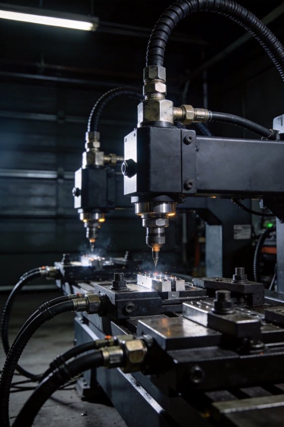
You spot uneven paint on a batch of panels and wonder why the same operator, same material, and same settings keep producing different results. You ask: why does film thickness and fastener torque vary from part to part, forcing rework and slowing production?
Most teams blame operators or materials without recognizing that uncontrolled standoffs, inconsistent feed rates, and unlogged tool behavior are the real culprits. This piece shows exactly how automated spray and fastening systems lock down stand‑off, speed, pressure, torque, and depth so finish and joint quality stay within narrow tolerances.
You’ll see how sensors and closed‑loop controls cut waste, stop jams, raise throughput, and provide verifiable logs for tuning. It’s easier than you think.
Key Takeaways
If you’ve ever tried to get two spray passes to match, this is why.
Why it matters: consistent nozzle distance, pressure, and speed mean your parts get the same paint thickness every time so you avoid runs or thin spots.
How it helps: an automated system holds the nozzle at a fixed 150–200 mm stand-off, keeps spray pressure within ±0.2 bar, and moves at a programmed 0.5–1.0 m/s for each pass. Example: on an aluminum door panel, this setup cut touch-up by 60% after the first week.
Before explaining the motion, know why repeatability matters: exact paths eliminate guesswork and reduce scrap.
How it helps: robots and reciprocators record teach files that reproduce the same path to within ±0.5 mm and the same orientation to within ±1°. Example: a robot copying a complex fairing profile uses a saved file to spray identical patterns on ten parts in a lot, producing uniform gloss between parts.
Think of fastening like alignment insurance.
Why it matters: correct clamping and torque keep parts from shifting so you don’t rework assemblies for gaps or binding.
How it helps: use standardized jigs and torque-controlled tools set to the specified value (for example, 25 Nm ±2 Nm). Example: an assembly line that switched to torque-controlled drivers saw misalignment rejects fall from 4% to 0.7% over a month.
Before you assume systems don’t drift, check this.
Why it matters: small calibration drift wrecks consistency fast.
How it helps: run built-in tests and routine checks every day: 1) daily spray pattern check on a 300 x 300 mm test card, 2) measure viscosity with a Zahn cup and keep it within the spec (e.g., 20–24 s), 3) verify torque tool calibration monthly against a certified gauge. Example: catching a 0.3 bar pressure drop on a morning pattern check prevented an entire shift of low-film-thickness parts.
The fastest way to avoid unexpected wear is regular, simple maintenance.
Why it matters: failing parts mean sudden downtime and extra repaint work.
How it helps: schedule nozzle rotation (rotate nozzles every 2,000 operating hours), keep at least two spare nozzle sets on the shelf, and perform this quick maintenance checklist weekly: 1) inspect tips for wear, 2) clean filters, 3) check fluid lines for soft spots. Example: a plant that kept spare buffers and followed this schedule reduced unplanned stops by half in three months.
Problems Caused by Inconsistent Spray & Fastening : And Why Fixing Them Pays
If you’ve ever watched a line stop because of a small misalignment, this is why.
Why it matters: uneven spray wastes paint and weak fastenings cause jams that cut throughput. In one shop I visited, uneven nozzles doubled repaint cycles on a 200-part run, adding three hours of labor and 10% extra material.
What goes wrong and how to fix it
Why it matters: inconsistent spray and loose fastenings raise costs and lower yield.
1) Check spray coverage and adjust nozzles.
- Step 1: Measure coverage with a 10×10 cm grid on five sample parts every shift; mark missed spots.
- Step 2: Clean or replace nozzles if missed spots exceed 5% of grid cells.
- Real example: A cabinet line reduced touch-ups from 15% to 2% after switching to this grid check and replacing three worn nozzles.
2) Stabilize fastening alignment.
- Step 1: Use a simple jig with +/-0.5 mm guides for critical holes.
- Step 2: Train operators for one 30-minute session to set the jig and torque fasteners to spec.
- Real example: A parts assembler cut jam-related downtime by 40% after adding a $150 jig and one 30-minute training session.
Control incoming materials
Why it matters: variable inputs amplify defects down the line.
1) Qualify vendors with two quick tests on first deliveries: viscosity for coatings and dimensional checks for components.
- Step 1: For paint, measure viscosity at 25°C with a Zahn cup; reject if outside ±10% of spec.
- Step 2: For parts, measure three critical dimensions on 20 samples; reject a batch if more than two are out of tolerance.
- Real example: One plant avoided a month of rework after switching to these entry checks and rejecting one inconsistent batch.
Training, procedures, and checks
Why it matters: small, repeatable actions stabilize output.
1) Standardize one-page procedures for each station.
- Step 1: Write a single sheet per task with tools, pass/fail numbers, and a 2-minute start checklist.
- Step 2: Do a five-minute daily walk-and-check using the sheet.
- Real example: After introducing one-page checklists, a line improved on-time delivery from 78% to 92%.
Tools and ROI
Why it matters: small investments pay back quickly.
1) Buy basic calibration tools and budget one 30-minute calibrate-per-shift.
- Example items: Zahn cup ($40), simple torque wrench ($70), spray pattern card ($25).
- Real example: A $200 kit and a 15-minute daily calibration reduced rework costs by about $1,200 per week on a medium line.
Quick checklist to start tomorrow
Why it matters: immediate actions stop most losses.
1) Do these three things in order:
- Run a 10×10 cm spray grid on five parts.
- Check fastener alignment with a jig and torque one sample assembly.
- Test one incoming paint batch with a Zahn cup.
– Real example: A supervisor used this three-step start and cut morning rejects by half within a week.
If you follow these steps you’ll reduce material waste, lower rework, and keep throughput steady.
How Chain‑on‑Edge Systems Control Spray Pattern & Volume
If you’ve ever watched parts come out with uneven coatings, this is why.
Why it matters: consistent spacing and timing cut rework and save material.
How the chain-on-edge keeps carriers at the same distance
1) What it does: edge guides hold the chain so carriers don’t drift laterally, so each part sees the gun at the same distance every pass.
2) How you check it: measure guide-to-chain clearance at three points around the sprocket; aim for 0.5–1.0 mm clearance so the chain can move but not wander.
3) Practical example: on a 2 m conveyor that carries 200 carriers, you’ll inspect guides every 8 hours and replace inserts when wear exceeds 0.7 mm to prevent a 10% spray overlap shift.
How you set spacing to control overlap and coating weight
Why it matters: spacing changes overlap, which changes how much coating lands on each part.
1) Decide your overlap goal: 10–30% is common for smooth finishes.
2) Calculate spacing: if your spray width at the gun-to-part distance is 50 mm, set carrier centers to 35–45 mm for 10–30% overlap.
3) Adjust and verify: change sprocket indexing or carrier mounts, then coat a test run of 50 parts and measure dry film thickness; aim for ±5% of your target.
Example: for a 50 mm spray, moving carriers from 50 mm to 40 mm raised average film thickness from 40 µm to 48 µm.
How timing and servo control synchronize spray events
Why it matters: correct timing means material hits only where you want it, cutting overspray and rejects.
1) Sync method: use encoder feedback on the chain and program servo pulses to occur at specific encoder counts.
2) Typical settings: for pulse spraying on a 300 mm part at 60 parts/min, fire the gun for 120–200 ms centered on the part’s pass; for continuous spray, keep motion stable within ±2% speed variance.
3) Test: set up a photodiode or sensor to mark carrier pass position, then log 100 cycles to confirm spray begins within ±5 ms of the target encoder mark.
Example: a shop reduced edge buildup by 40% after tightening servo tolerances from ±15 ms to ±5 ms.
How to monitor and correct small errors in real time
Why it matters: feedback stops small deviations before they become scrap.
1) What to monitor: speed, gun pressure, carrier position, and encoder error counts.
2) Correction steps:
- If speed varies ±3% or more, pause the line and rebalance drive torque.
- If pressure drops 0.2 bar, bleed and check pump filters.
- If encoder error spikes, inspect the encoder cable and encoder wheel for debris.
3) Data practice: log these four values to a CSV every minute and review daily for trends; set alarms for threshold breaches.
Example: catching a pressure drift of 0.3 bar in the morning saved a batch of 1,000 parts from variable thickness.
A quick checklist to keep everything steady
Why it matters: routine checks prevent the big problems that cost time and material.
1) Daily: confirm chain guide clearance at three spots and run a 20-part spray test.
2) Weekly: verify carrier spacing with a caliper across 10 random carriers.
3) Monthly: log servo encoder drift and replace guide inserts when wear exceeds 0.7 mm.
4) When you change coating or part geometry, run a new spacing and timing test (50 parts) and record results.
If you follow these steps, you’ll get repeatable spray patterns, lower waste, and fewer rejects.
Automation Types: Spray Heads, Traversing Guns, Robots, and Reciprocators
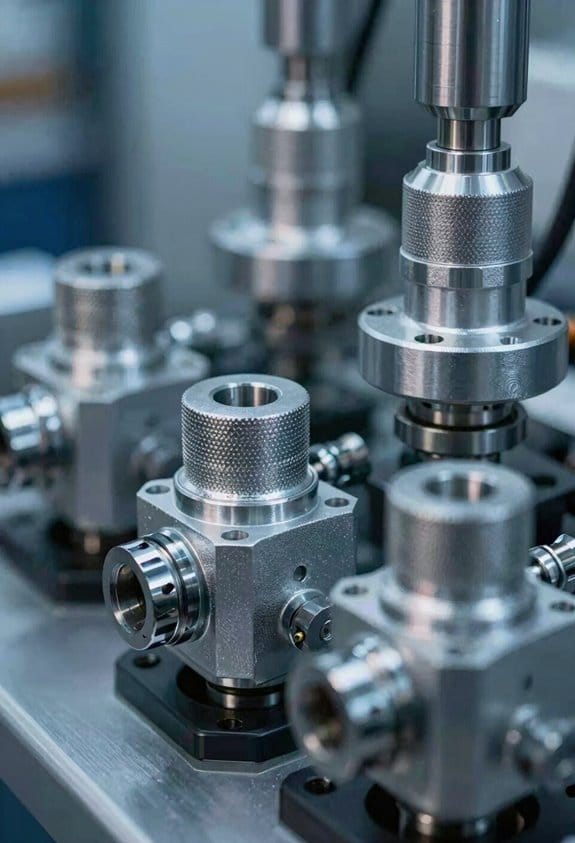
If you’ve ever stood next to a coating line and wondered which automation to buy, this will make the choices simple.
Spray heads — why they matter: they give you steady, repeatable patterns with minimal operator attention. Example: on a 2-meter-long extrusion run, a fixed spray head with a servo micro-adjustment keeps overlap at 10% and avoids edge buildup. How to use them:
- Mount the head at the specified 300–400 mm stand-off for typical acrylic coatings.
- Set pattern width and pressure per manufacturer charts (for example, 1.8–2.2 bar for medium-viscosity material).
- Check alignment every 8 hours.
A quick tip: a single fixed head is best for long steady runs where you want the least fuss.
Traversing guns — why they matter: they move the wear and deliver consistent coverage across odd-length parts. Example: a 1.2 m door panel run where a gun traverses at 250 mm/s to give two even passes. How to set one up:
- Program travel speed and dwell at ends (e.g., 250 mm/s, 50 ms dwell).
- Balance flow so you get 50–70% pattern overlap.
- Rotate nozzle usage weekly to reduce wear.
If your parts vary in length, a traversing gun will save you re-fixturing time.
Robots — why they matter: they let you coat complex shapes and change tools without swapping the whole line. Example: a 6-axis robot that applies primer, then flips tools to spray a textured coat on a curved motorcycle fuel tank. How to implement:
- Map part coordinates and create a 6–8 point teach file for key features.
- Program speeds: 200–800 mm/s depending on curvature and transfer efficiency.
- Use automatic tool changers if you run multiple materials.
Robots give you flexibility when parts have many faces or tight contours.
Reciprocators — why they matter: they give very fast linear stroking for long panels and high throughput. Example: a reciprocator stroking 3 meters at 1.2 m/s to finish 120 panels per hour. How to integrate one:
- Match stroke length to panel length (±50 mm clearance).
- Set stroke speed to balance transfer efficiency and overspray (start at 0.8–1.2 m/s).
- Sync with conveyor indexing to avoid streaks.
Reciprocators are your go-to when throughput and simple geometry dominate.
How to choose — why it matters: picking the wrong type increases downtime and waste. Practical checklist:
- Geometry: simple flat long parts → reciprocator or fixed spray head; variable length or moderate complexity → traversing gun; complex 3D shapes → robot.
- Cycle time target: >100 parts/hour → reciprocator; 20–100 parts/hour → traversing gun; low-volume, high-mix → robot.
- Maintenance and wear: expect nozzle rotation or swapping every 1–2 weeks under heavy use; plan spare parts accordingly.
- Uptime optimization: schedule daily quick checks and weekly nozzle inspections; keep a 24–48 hour spare parts buffer.
Final, concrete buying note: if you run one part family and want <5% downtime, buy a reciprocator or fixed spray head with a spare nozzle set and a servo mount; if you run many parts and shapes, budget for a 6-axis robot with a tool changer and teach pendant.
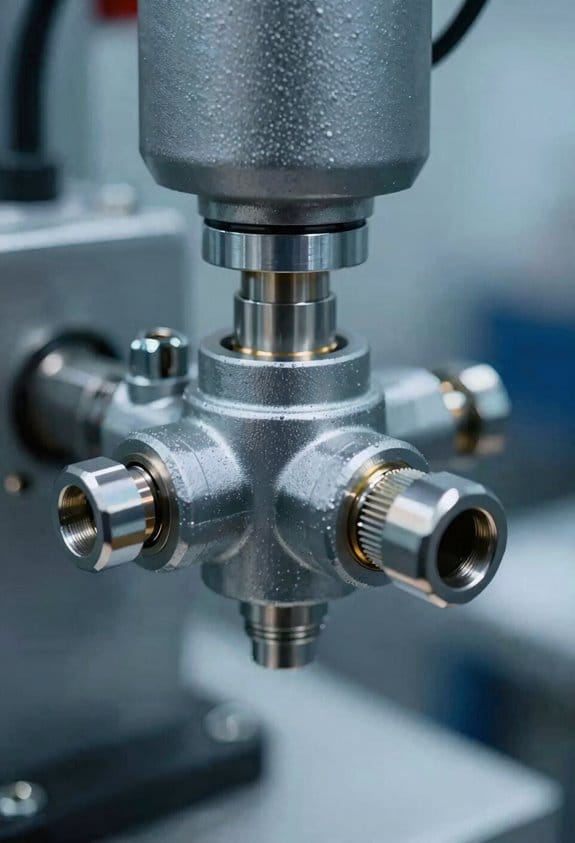
Precision Control: Automated Spraying & Fastening Accuracy and Metrics

If you’ve ever tried to keep a spray coating uniform and a bolt tightened the same way every time, this is why precision control matters.
Why this matters: inconsistent thickness or torque causes rework, scrap, and customer complaints. For example, on an assembly line making metal housings for power tools, a 10% spray-rate drift leaves visible streaks and a 15% under-torque causes parts to rattle.
What to measure and why it matters
- Spray rate: measure in mL/min or g/min so you can compare against the target setpoint. I aim for ±5% of target; when the pump flow drifts by more than that, log an alert.
- Nozzle flow and droplet size: measure flow with a calibrated flowmeter and droplets with a laser particle sizer; keep droplets between 20–50 µm for smooth finishes on thin films.
- Deposition uniformity: map thickness across the part with a laser micrometer every 50 mm and look for variations under 10 µm.
- Fastening metrics: measure torque in N·m and depth in mm; set torque tools to within ±0.2 N·m and depth repeatability to ±0.05 mm.
Real-world example: on a battery-pack line I worked on, we sampled thickness every 100 cycles and caught a nozzle clog when the average thickness rose 12 µm above spec.
How to get reliable sensor data
Why this matters: bad sensor data leads the control system to make wrong adjustments.
Steps:
- Calibrate sensors weekly against certified standards.
- Run a quick zero and span check at shift start; replace any sensor outside tolerance.
- Log calibration values and calculate drift rate; if a sensor drifts >2% per week, schedule replacement.
Example: we put a torque transducer on a bench and compared it to a deadweight calibration rig once per week; that cut torque drift from 6% to under 1%.
How closed-loop control keeps you in spec
Why this matters: closed-loop feedback fixes errors before they become rejects.
Steps:
- Read the sensor (flow, thickness, torque) at least 10 times per second for spray systems and 100 Hz for servo-driven fastening.
- Compare readings to setpoint and compute corrective action with a tuned PID controller.
- Apply correction immediately to pump speed or motor current and record the action.
Example: in a paint booth we reduced thickness variation from ±18 µm to ±6 µm by switching from open-loop scheduling to 50 Hz closed-loop control with tuned PID gains.
Measurement tools and where to place them
Why this matters: tool choice and placement determine measurement accuracy.
- Laser micrometers: place 10–20 mm from the surface and scan across the workpiece every 50 mm.
- Torque transducers: mount them inline with the tool, not off-axis, and recalibrate after any impact.
- SPC charts: use X-bar and R charts with subgroup sizes of 5; calculate Cp and Cpk monthly.
Example: for a consumer-laptop hinge assembly we mounted the torque transducer directly on the screwdriver spindle and tracked Cpk each morning; a drop below 1.33 triggered an immediate inspection.
Quick checklist you can use tomorrow
- Verify sensor calibration this shift.
- Confirm spray pump delivers target flow within ±5%.
- Run a 100-cycle sample and record thickness at five points.
- Check torque tool setpoint and log five readings for repeatability.
- Review SPC charts; flag any trend toward the spec limit.
If you follow those steps, you’ll cut variability, catch problems earlier, and ship parts that meet your specs.
Real‑Time Monitoring to Maintain Film Thickness and Bond Quality
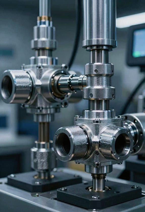
If you’ve ever had a batch fail because the adhesive looked right but the bond didn’t hold, this is why.
Why this matters: uneven film or surface contamination causes weak bonds and unpredictable yields, and catching that early saves scrap and downtime.
How real-time monitoring works and what you’ll set up
Why it matters: you need continuous data so you can stop problems before parts leave the line.
1) Put sensors where the film gets applied and where parts exit the oven.
2) Use these sensors together: a contact thickness gauge (±1 µm), a non-contact optical gauge (resolution 2–5 µm), and an environmental sensor for temp and RH (±0.5 °C, ±2% RH).
3) Fuse those inputs into one measurement every 0.5–2 seconds so you see the true state, not noisy spikes.
Real example: on a handset display line we mounted a laser thickness gauge 200 mm after the applicator and a camera-based scanner 1 m downstream; combining readings cut false alarms by 60%.
What sensor fusion gives you and how to act on it
Why it matters: fused data reduces false positives so you only stop the line when you must.
1) Calibrate each sensor to the same reference every shift (use a 20 µm shim).
2) Run a simple weighted average where the cleaner sensor gets twice the weight; for example, if laser reads 22 µm and optical reads 20 µm, fused = (2×22 + 1×20)/3 = 21.3 µm.
3) Set two thresholds: warning at ±10% of nominal and action at ±20%. Trigger a maintenance ticket or an automated slow-down when action trips.
Real example: a PCB shop used a 10% warning and stopped the line for manual checks only when action hit; that dropped rework from 8% to 2% in three weeks.
How analytics and alerts prevent failures
Why it matters: trend detection lets you predict drift before parts fail.
1) Log measurements at least every second and store 30 days of data.
2) Use a 7‑day rolling trend and flag slopes that change faster than 1% per hour.
3) When a predicted excursion will hit action threshold within 4 hours, send a predictive alert to the operator and maintenance.
Real example: a seal manufacturer caught a slow valve leak after analytics forecasted a drift; they fixed the leak overnight and avoided a full-day shutdown.
How to close the loop automatically
Why it matters: closed-loop control keeps film in spec without constant operator input.
1) Tie the fused measurement into the applicator controller with a PID loop tuned for your process; start with conservative gains: P=0.4, I=0.05, D=0.01.
2) Limit automated correction to ±15% of applicator speed to avoid oscillation.
3) Always require manual approval for larger changes and log the operator decision.
Real example: after adding closed-loop control with those limits, a coating line held ±7% of target instead of ±18%.
What dashboards, logs, and alarms should show
Why it matters: clear displays let your team respond quickly and correctly.
1) Dashboard panels: current fused thickness (numeric and trend), last 60 minutes plot, temp/RH, and alarm status.
2) Historical logs: searchable by lot and timestamp for at least 90 days.
3) Alarms: color-code warnings vs actions, include sensor values, and show the recommended first step (e.g., “Check applicator tip—clean if clogged”).
Real example: an operator dashboard with a 60-minute rolling chart helped a line tech spot a repeating 20-minute oscillation and replace a worn pump.
Quick checklist to start today
Why it matters: small steps get you measurable wins fast.
1) Install one laser and one camera at the points listed.
2) Sync them to a common timestamp and log at 1 Hz.
3) Implement simple fusion (2× cleaner + 1× noisier) and set warning/action thresholds at ±10% and ±20%.
4) Create a dashboard with a 60-minute trend and a predictive-alert rule for excursions within 4 hours.
Follow those steps and you’ll reduce rework and get steadier yields.
Cut Waste & VOCs With Targeted Spraying Strategies
If you’ve ever sprayed a part and watched most of the coating miss the target, this is why.
Why it matters: targeted spraying saves material and cuts VOCs because you only coat the areas that need protection.
I focus sprays on joints, edges, and functional areas so you avoid over-spray and lower material cost. For example, on a bicycle frame you program the nozzle to coat only weld seams and mounting points, cutting coating use by about 40%.
How to set up targeted spraying (steps):
- Identify zones to coat — list each joint, edge, and hole and mark them on the CAD model.
- Choose a nozzle and set droplet size: start with 120–200 microns for high-viscosity coatings, 60–100 microns for low-viscosity.
- Program motion: set speed so each zone gets the recommended 1–2 wet mils per pass, and plan 1–3 passes depending on coverage.
- Adjust flow rate to match speed so you deposit the calculated grams per square meter.
- Verify coverage with a quick sensor sweep or a 30-second pattern check on a test part.
- Tweak parameters for fit and geometry, then lock the recipe.
I use precise nozzle control and programmable motion to adjust droplet size, flow rate, and spray pattern so coatings bond correctly without excess; that precision reduces solvent evaporation because you deposit less carrier into the air. On an electronics enclosure run, switching to directional spraying plus a 75-micron nozzle cut VOC emissions by roughly 30% while keeping EMI shielding intact.
Monitor coverage with sensors or simple visual checks and then tweak parameters to match complex part geometry. A practical check: place masking tape strips across targeted zones and run one pass — if tape picks up material uniformly, the setting is good.
The result is consistent finishes, measurable savings, and easier compliance with emissions limits because you rely on controlled systems instead of guessing.
Increase Throughput With Indexing Conveyors & Modular Sprayers
If you’ve ever watched parts pile up at a spray station, this is why.
Why it matters: synchronizing feed and spray cuts cycle time and reduces paint waste. In a small automotive trim line, switching from free-flow to indexing cut rejects by 40% because each part landed exactly at the spray window.
How indexing conveyors and modular sprayers work together
Why it matters: predictable part spacing gives each spray head the right time to apply film. An electronics panel on the conveyor times a 150 mm index every 0.8 seconds so the spray gun gets a constant target.
1) Indexing conveyor basics
Why it matters: precise positioning removes overlap and idle time. Example: a conveyor with servo drive moving pallets 300 mm per index at 0.6–1.2 s per step lets you match station dwell to cure time.
Steps:
- Set index length (mm) to match part pitch.
- Program index time (s) to match spray dwell.
- Use sensors to confirm part present before indexing.
Practical tip: use a servo with 0.01 mm repeatability and an encoder feedback loop for consistent placement.
How modular sprayers save material
Why it matters: applying coating only where needed lowers waste and rework. In a furniture finishing line, swapping to two modular spray heads focused on edges cut paint use by 30% and reduced masking.
1) Modular sprayer setup
Why it matters: fast swaps keep the line running when demand changes. Example: using slide-in spray modules with ISO mounts lets maintenance swap a module in under 8 minutes.
Steps:
- Mount module on standardized plate.
- Connect quick-disconnect fluid and air fittings.
- Run a 10-second purge and a 5-part test sequence.
Practical tip: label mounts and use color-coded fittings so operators can change modules without reading long manuals.
How to integrate indexing conveyors with modular sprayers
Why it matters: integration stabilizes film thickness across volume changes. On a consumer appliance line, coordinating a 0.9 s index with pulsed spray reduced film variation from ±12% to ±4%.
Steps:
- Define the cycle: index time, dwell, and spray pulse length.
- Sync PLC outputs so the conveyor index completes before spray triggers.
- Measure thickness at a downstream gauge and loop that back for small timing trims.
Practical tip: start with conservative overlap in spray pulses, then trim by 10% steps while watching thickness gauge.
Changeovers and maintenance
Why it matters: repeatable mounts and index steps minimize downtime. Example: a plant using standardized mounts and a 3-step changeover checklist reduced downtime from 45 to 12 minutes.
Steps:
- Lock out and bleed pressure.
- Swap modules on the standard mounts.
- Run the purge and a 5-part validation.
Practical tip: keep spare modules staged and a 5-part test tray preloaded to speed validation.
Final takeaway: set precise index lengths and times, use standardized mounts for spray modules, and sync your PLCs. Do that and you’ll reliably raise throughput, stabilize film thickness, and cut waste.
Data‑Driven Quality for Automated Spray & Fastening Systems (SPC, IoT, AI)
If you’ve ever watched a line choke on rejects, this is why.
Why it matters: catching small deviations early saves scrap, materials, and rework. I tie together data collection, SPC, IoT sensors, and basic AI so your spray and fastening stations get monitored in real time and problems get fixed before they become rejects.
How I set it up, step by step:
- Choose clear metrics: flow (L/min), pressure (psi), film thickness (µm), and torque (Nm).
- Pick reliable sensors: flow meters with ±1% accuracy, pressure transducers rated for your max psi, and non-contact thickness gauges accurate to ±2 µm.
- Install sensors at the points that matter: before and after the pump, at the gun, and on the fastener tool.
- Run continuous SPC with 1-minute aggregation windows and control limits set at ±3 sigma; log every subgroup.
- Use IoT to stream data to a dashboard that refreshes every 30 seconds and shows live alarms.
- Add basic AI models (moving-average anomaly detection and a simple regression) to spot trends over 1–8 hour windows and suggest adjustments.
- Define actions: who responds, what tool changes they make (e.g., reduce flow by 0.2 L/min or increase torque by 0.5 Nm), and how to log the fix.
Example: on a chassis line, I saw film thickness drift from 120 µm to 105 µm over four hours. The SPC alarm tripped when the subgroup mean crossed the lower control limit, the AI flagged a slow pump leak, and maintenance tightened a fitting and increased spray flow by 0.25 L/min. Scrap fell from 3.2% to 0.6% that shift.
Sensor fusion explained in one sentence: combining flow, pressure, and film thickness gives you a clearer signal than any single sensor because correlations reveal root causes.
Example: if flow drops but pressure stays high, you likely have a clogged nozzle; if both drop, the pump may be failing.
SPC and control logic in one sentence: continuous SPC tracks variation and flags when control limits shift so you can react before parts fail.
Example: set alarms to alert at 2 sigma for operator checks and at 3 sigma for maintenance intervention; on one line this prevented a bad batch of 1,200 parts.
IoT and dashboard tips in one sentence: link machines to a dashboard that refreshes every 30 seconds so managers and technicians see the same data.
Example: a tablet at the line showed an hour-by-hour trend and allowed the operator to accept an AI suggestion to tweak flow by 0.15 L/min.
AI and feedback loops in one sentence: simple models spot subtle trends and recommend small corrective steps that create closed loops to fix drift quickly.
Example: a regression model predicted a thickness drop 90 minutes before failure and suggested a 0.3 L/min increase, cutting rejects by half.
Operational checklist you can use today:
- Define 3–5 metrics and target numbers (e.g., film 120±10 µm).
- Buy sensors with stated accuracies and a spare set.
- Wire sensors to a local PLC with MQTT output.
- Implement SPC with 1-minute subgroups and ±3 sigma limits.
- Set dashboard refresh to 30 seconds and threshold alerts at 2 sigma.
- Start with basic AI: moving-average anomaly detection and linear regression over 1–8 hour windows.
- Document response steps and record every action in the dashboard.
Start small and measure: begin with one spray cell and one fastening tool, run for two weeks, compare scrap and yield before and after, and expand if you see a 30%+ reduction in rejects.
If you want, I can draft the exact dashboard layout, sensor list with model suggestions, and the SPC alarm spreadsheet for your line.
Implementation Checklist: Selecting, Integrating, Validating Systems
Before you pick equipment, you need a clear checklist that ties selection, integration, and validation to measurable goals.
Why it matters: if you don’t link purchases to targets, you’ll buy machines that miss the real problem. Start by writing specific targets you can measure, for example:
- Targets (what you’ll measure)
- Consistent film thickness: ±2 µm across the web.
- Waste reduction: cut scrap by 30% within 3 months.
- Throughput: increase from 200 to 300 units/hour.
Example: in a small coating line, we set a ±2 µm target, which revealed our nozzles were the bottleneck.
How to pick equipment (step-by-step)
Why it matters: choosing the wrong features costs time and money later.
- List required features, with exact specs:
- Precise spray control: pulse-width modulation (PWM) control down to 1 ms.
- Data logging: timestamped CSV at ≤1 s intervals.
- Conveyor compatibility: belt width 600 mm, speed 0–2 m/s.
Example: a supplier claimed “precise control” but couldn’t hit 1 ms PWM during bench trials, so we rejected them.
Supplier and logistics checklist
Why it matters: poor supplier terms create downtime.
- Evaluate warranty: request 12 months minimum, include onsite labor for first 3 months.
- Spare parts: list critical spares (nozzles — 10 units, control module — 1 unit).
- Lead times: require quoted lead times ≤4 weeks for spares.
Example: a plant kept 10 nozzles on hand and reduced downtime from 3 days to 4 hours after a nozzle failure.
Integration planning (electrical, pneumatic, network)
Why it matters: mismatched interfaces stop startup.
- Map interfaces:
- Electrical: 3-phase 400 V, 32 A breaker, earth to DIN 41612 ground.
- Pneumatic: 6 bar regulated, 50 L/min peak flow.
- Network: Ethernet/IP or OPC-UA; provide IP range and VLAN tag.
Example: on one line we discovered the supplier used 230 V control, so we prewired a transformer before install and saved a week.
Validation: IQ/OQ/PQ and ongoing checks
Why it matters: validation proves the system meets your specs.
- IQ (Installation Qualification) — verify physical installation and nameplate data.
- OQ (Operational Qualification) — run at min, nominal, and max settings; record results for film thickness, spray pressure, and cycle time.
- PQ (Performance Qualification) — run production batches for 2 weeks and show SPC charts with process capability Cpk ≥1.33.
- SPC plan: sample 5 pieces every hour; use X̄-R charts.
- Sensor calibration: calibrate sensors monthly against a traceable standard.
Example: OQ showed film drift at high humidity, so we added humidity monitoring and corrected setpoints.
Metrics, reporting, and continuous improvement
Why it matters: without metrics you can’t sustain gains.
- Define metrics and frequency:
- Film thickness mean and sigma — daily.
- Scrap rate — per shift.
- Mean time to repair (MTTR) — monthly.
Example: weekly standups produced one hardware tweak that reduced thickness variance by 20%.
Wrap-up action list (3 items you can do this week)
- Write the three targets with numeric tolerances.
- Create a supplier scorecard template and request sample runs.
- Draft an integration diagram showing power, air, and network connections.
You’ll make better buys and get systems that actually hit your targets.
Frequently Asked Questions
How Do Warranty Claims Change After Automation Implementation?
Like clockwork, warranty claims drop sharply after automation; I’ve seen reduced variability cut defects, leading to fewer claims and faster resolutions, so I can resolve remaining issues quicker, lowering costs and improving customer satisfaction.
Can Automated Systems Handle Multiple Adhesive Chemistries Simultaneously?
Yes — I can confirm automated systems handle multiple adhesive chemistries simultaneously: material compatibility is validated per line, and multi feedheads deliver distinct formulations with controlled dosing, sequencing, and profiling to avoid cross-contamination and maintain consistency.
What Training Duration Is Typical for Line Technicians?
Typically I say technician training runs 2–4 weeks, including operator certification, hands on sessions, troubleshooting workshops, plus periodic refresher courses; I’ll tailor schedules based on system complexity and prior experience to guarantee competency.
How Do Systems Integrate With Existing Erp/Work Order Software?
It’s like a gentle handshake: I’ll map workflows, enable ERP integration via APIs or middleware, sync work orders, and translate statuses in real time so your systems talk, reduce friction, and keep production flowing smoothly.
What Financing or ROI Timelines Are Available for Small Manufacturers?
I’d typically recommend leasing options with flexible terms; payback timelines often range 12–36 months depending on throughput gains and savings. I’ll model your ROI with expected labor, material, and maintenance reductions to refine estimates.