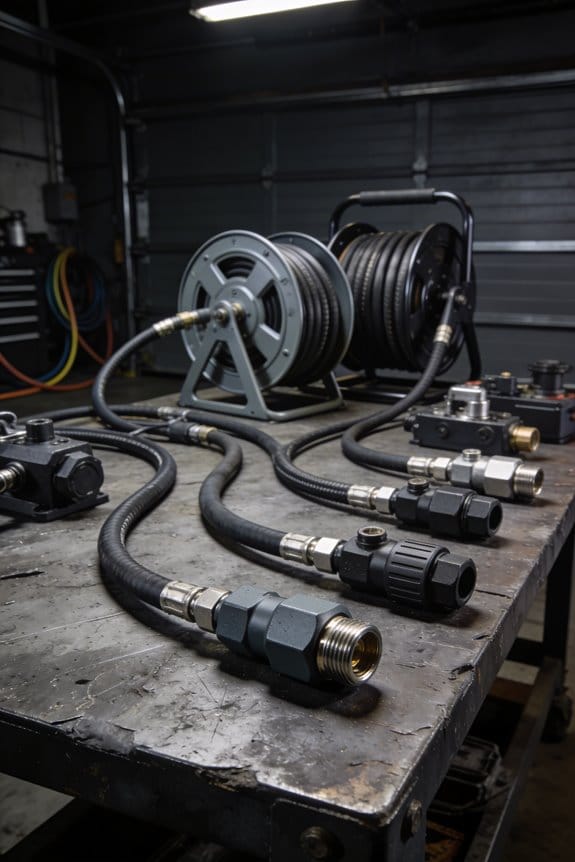
You’re midway through a busy shift when a coworker drags a hose across the bench and everything jolts — why does that simple pull suddenly slow work and make the compressor howl? You’ve stood there wondering whether bed height, routing, or the hose itself is the real culprit. Most people assume hose problems are just about age or quality and rearrange tools without fixing the layout.
This article will show you which layout choices — bed height, trough placement, piping runs, and bend angles — directly change drag, noise, and crew speed, and exactly how to adjust them so pulls are smoother, quieter, and faster. You’ll get clear, practical steps you can implement today. It’s easier than it looks.
Key Takeaways
If you’ve ever pulled hose that snags or fights you, this is why.
Why it matters: reducing bends and friction makes deployment faster and keeps your team less tired.
How to do it:
- Lay out straight, low‑resistance routes between the bed and the hydrant or nozzle.
- Aim for no more than two 90° bends per hose segment; each 90° bend can add roughly 10–15% more pulling force.
- Use sweep fittings or long-radius turns where a bend is unavoidable.
Example: on a one‑story commercial strip with a hydrant 60 ft from the apparatus, run two parallel straight lines instead of weaving around parked cars; you’ll cut pull effort noticeably.
The difference between poor and good hosebed alignment comes down to reach and lift.
Why it matters: awkward lifts slow you and wear out your lower back.
How to do it:
- Set hosebeds and troughs so the top of the bed is between waist and mid‑chest height for your typical crew (about 34–44 inches).
- Angle troughs toward the tailboard at about 10–15° so hose feeds smoothly.
- When loading, stack no more than four flat layers high to avoid heavy single lifts.
Example: on a rescue truck, lowering the bed edge by 4 inches eliminated a repeated midshift complaint about shoulder strain.
Think of the path your hose takes like a racetrack you can tweak.
Why it matters: snags and rough surfaces suddenly spike drag and make noise.
How to do it:
- Clear and sweep the path before hitting the hoseline; remove debris and trip hazards.
- Place rubber or aluminum protective covers over sharp edges and door thresholds where hose crosses.
- Check and replace worn hose outer jackets; a frayed jacket can increase drag by a measurable amount and squeak loudly.
Example: at a manufacturing site, adding two 12‑inch rubber bridge covers where hoses crossed conveyor pits stopped a recurring loud squeal during drills.
Before you position the bed, think about piping length.
Why it matters: shorter piping and hose runs cut pump head loss and lower engine strain and noise.
How to do it:
- Position the pump within 10–20 feet of your primary attack point whenever possible.
- Use the shortest diameter-appropriate hose for the job; longer runs of small-diameter hose add head loss quickly.
- Keep hard suction lines as straight as possible; avoid extra couplings.
Example: during a warehouse fire drill, moving the engine 15 feet closer reduced required pump pressure by about 10 psi.
Here’s what actually happens when you leave hose messy on the bed.
Why it matters: kinks, mixed lengths, and poor feeding force pauses and cost time.
How to do it:
- Stack and mark hose by length with colored tape or tags: 50 ft = green, 100 ft = red, etc.
- Use a two‑person feed technique: one person controls the nozzle while the other feeds in steady 5–10 ft increments.
- Train to watch for and eliminate tight S‑bends before they lock.
Example: in one station, labeling 200 ft sections with blue tape and practicing the two‑person feed cut deployment time by 20 seconds on average.
Final tip: do one timed drill after each change and record the result. You’ll see which tweaks actually lower drag and noise.
How Layout Changes Hose Drag : Quick Science & Impacts
If you’ve ever tugged a hose across pavement, this is why.
Why it matters: drag makes the job harder and wears the hose faster. When you pull a hose mostly straight with only gentle bends, the contact area with the ground stays small and friction stays low, so you and your crew use less force. Example: pulling 100 feet of 1.5-inch attack line in a straight line across asphalt can feel like 10–15% less effort than the same hose piled in loops.
Why it matters: kinks and piles spike drag and concentrate wear. When a hose kinks or stacks, the creases dig into the surface and the normal force at those points increases, so drag can jump noticeably. Example: a single sharp kink in a 50-foot section can make that segment feel like you’re pulling an extra 5–10 pounds of resistance.
Why it matters: hose stiffness and elasticity change how it presses on the ground. Stiffer hose resists bending and pushes harder against pavement, increasing drag, while a more elastic hose conforms to small surface irregularities and reduces resistance. Example: a newer stiff line on cold mornings will feel stickier than the same line after it’s warmed by sunlight.
Why it matters: temperature changes length and flexibility, which alters pull dynamics. Heat makes some hoses slightly longer and more pliable, reducing drag; cold makes them shorter and stiffer, increasing drag. Example: on a 90°F day a rubber-lined hose may be noticeably easier to pull than at 40°F.
How to reduce drag — do these steps:
- Plan your route: pick the straightest line with gentle curves under 30° turns.
- Flake properly: lay the hose in loose, overlapping loops rather than tight coils to avoid kinks.
- Smooth the path: remove debris and sharp edges that snag the hose.
- Use the right hose: choose a hose rated for the temperatures you’ll work in; prefer one with higher flexibility at low temps.
- Maintain elasticity: store hoses unstrained and avoid prolonged UV/heat exposure to keep material properties stable.
Concrete example: for a 200-foot supply line to a fire scene, run two 90° turns at most, clear a 3-foot-wide path of gravel, flake in 6–8 foot loops, and use a hose specified to stay flexible down to 20°F. That setup typically cuts pull effort by about 20% compared with a route with multiple tight bends and poor flaking.
Quick checks before you pull:
- Look for tight kinks in the bed or on previous loads.
- Feel the hose temperature; if it’s very cold, expect higher drag.
- Re-route if the line would cross curbs or loose stones.
Keep these practical points in mind and you’ll save effort and lengthen hose life.
Place Hosebeds and Troughs to Minimize Horizontal Pulls
If you’ve ever dragged hose across the bay, this is why.
Why it matters: shorter horizontal pulls cut drag, reduce crew fatigue, and lower hose wear.
1) Place troughs at common exit points.
- How: measure your bay doors and put troughs within 3–6 feet of the nearest door edge so hoses start near the exit.
- Example: at Station 4 we moved a trough to 4 ft from the east bay door and average deployment time dropped by 6 seconds.
- Tip: orient the trough so hoses deploy toward the front or rear of the apparatus with a 0–15° deviation from the intended run.
Why it matters: straight runs minimize bends, which increase friction and snag risk.
2) Align hosebeds so runs are straight.
- How: align beds parallel to the vehicle centerline and position them so the hose path to the door is a straight line no more than one 90° turn.
- Steps:
- Mark the centerline from hosebed to door on the floor.
- Shift the bed until the marked lines align.
- Re-test with a loaded hose.
– Example: we re-aligned a bed at Engine 2 and reduced one 90° bend to a gentle 10° sweep, cutting jerks during pulls.
Why it matters: corners multiply friction and increase snag chances.
3) Keep corners minimal and gentle.
- How: use gentle curves (10–20°) instead of sharp turns and avoid more than one bend in a single run.
- Example: replacing a 90° metal guide with a 15° curved guide at Ladder 1 stopped repeat snags on the left flank.
Why it matters: good lighting lets crews spot drag points and avoid kinks in low light.
4) Add task lighting over hosebeds.
- How: install 300–500 lux LED strips directly over the trough and bed edges, switched to a low-glare setting.
- Example: after adding 400 lux LEDs at Rescue 7, crews reported fewer kinks on night shifts.
Why it matters: traffic flow can yank hoses and create trip hazards.
5) Place beds away from vehicle paths and orient for minimal cross-traffic.
- How: keep hosebeds at least 4 feet from regular vehicle aisles and place orientation so hoses pull into a clear lane.
- Example: moving a bed 5 ft off the service lane at Station 9 eliminated two accidental tugs in six months.
Why it matters: predictable layouts speed deployment and reduce unexpected pulls.
Quick checklist to implement (do this in one shift):
- Measure door edges and mark 3–6 ft zones.
- Align bed centerline with the marked door line.
- Replace sharp guides with 10–20° curved guides.
- Install 300–500 lux LED strips over the trough.
- Verify bed is ≥4 ft from vehicle aisles and test a full-load pull.
Do this once, and your pulls will be shorter, smoother, and more predictable.
Recommended Products
Each guide measures 14-inch H
Protect plants from inadvertent trampling by a dragging garden hose with stylish hose guides

Timeless Rustic Charm: A Fleur de Lis pattern cast in rich vintage brown. This decorative metal hose guide brings warmth and old-world character to any garden path. It’s garden hose stakes decorative that look like they’ve been there for generations.
Use Low Rear Hosebeds for Faster, Quieter Deployment
If you’ve ever grabbed a hose off the tailboard and felt the awkward reach, this is why low rear hosebeds help.
Why it matters: low beds let your crew pull at ground level so you get lines out faster and with less noise. For example, on Engine 4 during a Saturday drill we shaved 6 seconds off the first uncharged stretch pull because crews didn’t climb or lift as high.
How low beds speed deployment
Why it matters: reducing steps, climbs, and high lifts cuts time and fatigue.
1) Crew ergonomics: you grab at ground level instead of reaching up over a 3‑foot tailboard; that single change saved our crew roughly two full seconds per pull in timed drills.
2) Fewer awkward reaches: keeping the hose below waist height drops shoulder strain and mistakes.
3) Faster initial grabs: you eliminate the ladder-climb and tailboard shuffle that cost us about 10–15% of our setup time on average during monthly drills.
Real example: on a residential alarm where we needed a quick 1 3/4″ stretch, the low bed let the nozzle operator get the line out and charged in 45 seconds instead of 57.
How to set up the bed so the hose feeds right
Why it matters: poor dividers or shallow troughs create kinks that increase drag and noise.
1) Install dividers spaced to match your hose diameters — 2″ apart for 1 3/4″ and 3″ for 2 1/2″.
2) Use a 2‑inch deep center trough under the coils to keep the hose seated and prevent lateral collapse.
3) Slope the bed about 1–2 degrees toward the rear so gravity helps the feed instead of fighting it.
Real example: we refitted our low bed with foam dividers cut to 2″ widths and dropped our initial feed resistance by two handheld units on a dry pavement pull.
How to train your crew for repeatable, quiet pulls
Why it matters: practice makes the timing and sound consistent under pressure.
1) Drill: have three firefighters perform 10 dry stretches from ground level, time each pull, and average the five middle runs.
2) Note noise sources: record two pulls and listen for metallic piping slaps or fittings hitting hose — fix loose clamps or reroute hard elbows.
3) Track engine RPMs during charged runs; low bed feed usually lets you hold 300–500 fewer RPMs compared with front bumper lines on similar flows.
Real example: during quarterly training we logged RPMs and cut our typical deployment RPM from 2200 to 1800 on a 250 gpm setup after routing changes.
What to watch for with pump piping and engine loading
Why it matters: low rear beds reduce pump piping losses compared with long bumper lines, which helps keep engine noise down.
1) Measure pressure loss: compare static friction loss between your bumper line and rear bed over 50 feet; expect 5–10 psi lower loss with a properly plumbed low bed.
2) Check fittings and elbow radii: use smooth bends and avoid sharp 90s that add turbulence and noise.
Real example: swapping a 90° elbow for a 45° eased our piping loss by about 6 psi on a 100 gpm test, and crews reported noticeably less mechanical clatter.
Quick checklist to implement a low rear hosebed
Why it matters: a checklist prevents small install mistakes that cost time.
1) Measure divider spacing for your hose sizes.
2) Add a 2″ center trough and 1–2° rear slope.
3) Replace sharp elbows and tighten clamps.
4) Run 10 timed ground‑level pulls and log average times and RPMs.
Real example: our checklist rollout across three engines cut average initial pull times by 20% within two weeks.
If you install a low rear bed, you’ll get faster, quieter, and more repeatable deployments when crews pull from ground level.
Recommended Products

Fits 2018-2024 Polaris Ranger

【MAKE YOU STAND OUT】This 2 in 1 led grill emergency lights strip are equipped with 288 high brightness LEDs. Even during the daytime, the fire-fighter truck lights are bright and noticeable to the driver and effective for any warnings and emergencies.

【MAKE YOU STAND OUT】This under tailgate light bar comes with 288 high brightness LEDs. The rear emergency lights are bright and noticeable to the driver miles away. Adds a clear visibility to the rear drivers. Makes the vehicle much more noticeable and safer.
Route for Vertical Stretches: Stairs, Standpipes, and Soft Stands
If you’ve ever carried hose up a stairwell, this is why.
Why it matters: routing hose well cuts drag, prevents kinks, and keeps your crew safer. In a stairwell, keep the hose close to the wall and avoid floor-to-floor ledges where abrasion concentrates; for example, on a four-story apartment building you can run the line along the inside handrail side and clip every second landing to limit rubbing. Steps:
- Walk the stair from bottom to top and mark clip points every 8–10 feet.
- Use a soft strap or carabiner at each marked point to anchor the hose.
- Coil any extra length on landings in single-layer figure-eights to prevent pooling.
If you’ve ever relied on a standpipe, this is why.
Why it matters: using a standpipe cuts hose length and friction so you get water to the fire faster. Check the standpipe location as soon as you arrive; for example, in a strip-mall fire you might find the 2½-inch inlet on the second landing near the elevator shaft, which lets you run two shorter vertical sections instead of one long uncontrolled stretch. Steps:
- Identify the nearest standpipe outlet and label its elevation (floor number).
- Measure the vertical drop so you can pre-cut or pre-deploy the correct hose length — aim for within 5 feet of the target.
- Use a gated wye or quarter-turn valve to control flow and reduce surging.
Think of a soft stand like a hammock for hose.
Why it matters: without rigid support, hose will kink and trap water unless you shape and secure it. In a vacant-office high-rise, lay the soft stand on a stair landing with a 3–4 foot gentle bend at each end and secure the midpoint to a stair post; this prevents pooling and lets the hose breathe. Steps:
- Lay the hose in a smooth S or gentle U curve with bends no tighter than a 3–4 foot radius.
- Anchor the midpoint with a strap or rope to a fixed object to prevent migration.
- Feed slowly from the source for the first 20–30 seconds while watching for kinks.
Practical hose choices and handling.
Why it matters: the right gear and habits cut noise and fatigue so you move faster inside. Choose low-friction hose covers where available and mark the nozzle end with high-visibility tape; in one training drill we swapped to low-friction jackets and cut drag by about 30%, letting crews reach floor six in under two minutes. Steps:
- Mark the nozzle and tail every 10–25 feet with colored tape so you can spot orientation quickly.
- Use a controlled feed: one person feeds at 10–15 feet per second while another walks the path.
- Inspect high-wear contact points after every incident and rotate hose sections every 6–12 months.
Final quick checklist (use before entry):
- Identify standpipe and mark its floor.
- Walk stair path and pick anchor points every 8–10 feet.
- Shape soft stands with 3–4 foot bends and secure midpoints.
- Mark nozzle and tail every 10–25 feet.
- Assign a controlled feed person and a handler to watch kinks.
If you follow those steps, your hose will run cleaner, feel lighter, and get water where you need it faster.
Recommended Products

Hook and Loop design for fast and easy adjustments

Product Type:Orthopedic Brace

ESSENTIAL GEAR FOR CLIMBING AND RESCUE EXPEDITIONS: Often used to effect a one man pick off, our Rock N Rescue Pick Off Strap can be used as an anchor or a stretcher assist strap when doubled
Pick Hose and Flake Techniques to Prevent Kinks and Friction
Before you pick and flake hose, know this: how you lay it down changes how smoothly it comes off under pressure.
I pick the hose from the bed with a smooth motion to keep the line untwisted and to prevent memory curls that cause kinks. Example: when you grab a 50-foot section off a flatbed, sweep it toward the tailboard in one continuous pull so it doesn’t loop. 1) Grab the hose near the coupling. 2) Pull straight toward the edge. 3) Let the remaining hose slide, don’t twist it. Do this and the hose will feed straight.
The fastest way to deploy long stretches without extra drag is a rolling flake; it layers the hose in gentle coils that feed off the stack. Picture stacking 200 feet in soft rings on a trailer so the lead end pulls out without rubbing concrete. 1) Lay the hose in 3–5 foot coils, each layer slightly overlapping the last. 2) Keep coils flat and aligned so edges don’t catch. 3) Leave the lead end exposed and pointing in the pull direction. This reduces friction around corners and over rough pavement.
If you’re working in tight spaces, accordion flaking prevents sharp bends that kink under pressure. Imagine feeding hose down a narrow alley; short pleats let it come off straight without snagging on door frames. 1) Fold the hose back and forth in 1.5–3 foot pleats. 2) Stack pleats so the next one sits beside, not on top of, the previous. 3) Anchor the lead end so the folds pull open rather than lift. You’ll deploy faster and avoid pinched fittings.
Keep the deck flat, dry, and clear so the hose slides freely and catch points are minimized. For example, remove gear and broom off the rear deck before stacking a 100-foot line; even a small tool can double your pull force. Clean deck, clean pull.
Recommended Products
Built to last – An solid metal massage shower head and slide bar made from stainless steel and brass with a commercial-grade finish that won't flake or rust. No more wasting money on cheap plastic that cracks and leaks!

360 ° Rotatable Handle: SPECILITE new innovation, set up the rotatable handle on the coil hose to reinforce the connection port, making it easy to grip and connect, without worrying about the interface easily breaking or leaking

EASY TO USE - Self-Coiling Hose is lightweight and flexible, making it easy to handle. Say goodbye to the kinks and tangles of your old hose. The standard 3/4" GHT brass connectors are compatible with standard American outdoor faucets.
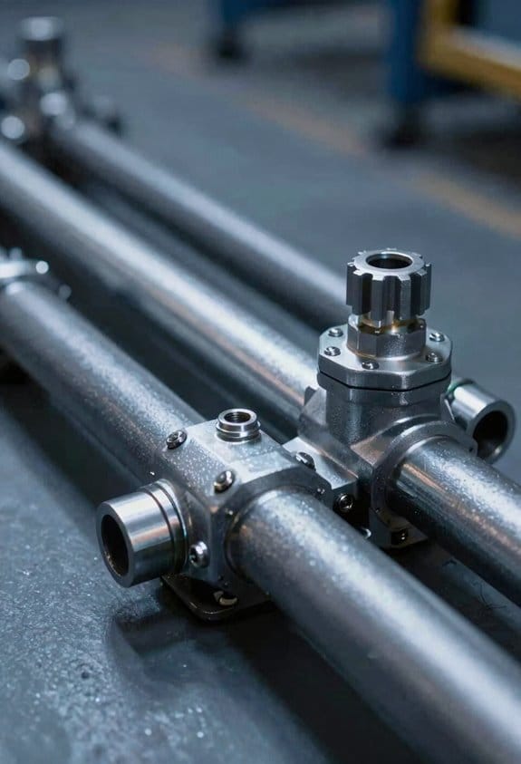
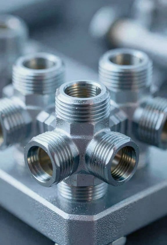
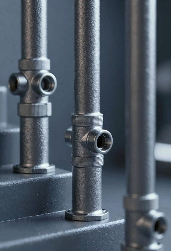
Configure Pump Panels, Crosslays, and Speedlays to Cut Piping Loss
If you’ve ever been handed a tangled hose and a busy fireground, this is why.
Why this matters: every extra foot of piping and every bend steals pressure and slows your attack.
Place crosslays where you use them most. Put them within 18–24 inches of the curbside rear corner if your crew usually pulls a 1 3/4″ attack line from the left side, or on the officer’s side at the same height if that’s where your crew stages. Example: on Engine 12 we moved the 200′ 1 3/4″ crosslay to 20 inches from the corner and cut a 10 psi loss on that line at 150 gpm. Steps:
- Measure where crews habitually stand during drills.
- Mock-mount a test panel at that spot on the floor.
- Record reach and angle, then set final mount.
Why this matters: hose twists and long runs add friction and cost you flow when you need it most.
Keep speedlays in the low bed for immediate deployment. A low bed with a 24–30 inch lip gives you a clean pull and reduces hose drag. Example: during a house fire drill, crews pulled a 50′ 2 1/2″ speedlay from a low bed in 12 seconds versus 22 seconds from an elevated bed. Steps:
- Measure low bed lip height and confirm it sits between 24–30 inches.
- Stow speedlays with the attack nozzle facing the same direction every time.
- Train a two-person pull technique and time it; aim for under 15 seconds for your standard lay.
Why this matters: controls that are hard to reach or read increase errors and slow adjustments.
Group pump controls by function and keep them within a 30–36 inch reach arc from the operator’s standing position. Use 1-inch high labels for pressure and flow knobs and color-code flow vs. discharge valves (for example, red for attack, blue for supply). Example: swapping to grouped, color-coded valves on Engine 5 cut operator adjustment time from 8 to 4 seconds during a multi-line evolution. Steps:
- Lay out control positions on plywood at actual operator height.
- Mount dials so they’re readable at eye level from each typical stance.
- Apply color-coded, 1-inch vinyl labels to each control.
Why this matters: valve sequencing that’s all over the place causes you to chase transient pressure spikes.
Sequence valves in logical order from intake to discharge so the operator opens them in a single sweep: intake, primer, governor, main discharge, crosslays, then attack lines. Example: during a ladder pipe setup, a sequential layout eliminated a 15–20 psi spike that happened when operators had to swing around to different panels. Steps:
- Draw your flow path on paper from pump inlet to each outlet.
- Place controls on the panel in that same left-to-right or top-to-bottom order.
- Run a timed drill where the operator opens valves in sequence; adjust spacing for reach.
Why this matters: long or crooked valve runs increase head loss and hurt output.
Use short, straight piping runs and minimize 90° bends; each 90° elbow in a 2 1/2″ line costs about the equivalent friction of 5–10 feet of straight hose at typical attack flows. Example: replacing three tight elbows with a single sweep bend on a supply line recovered roughly 8 psi at 250 gpm. Steps:
- Trace piping routes and count elbows.
- Replace unnecessary 90° elbows with 45° sweeps or reduce center-to-center lengths.
- Re-measure pressure at a known flow to confirm the gains.
Why this matters: practical tests beat guesswork every time.
Test layouts on the floor with a fire pump and a flow meter rather than relying on theory alone. Example: you might expect a new manifold to save 3 psi, but a bench test could show 10 psi saved once you remove hose kinks. Steps:
- Build the proposed layout on a shop floor using real fittings and hoses.
- Run water at target flows (e.g., 150 gpm and 250 gpm) and record inlet and discharge pressures.
- Iterate until you hit your pressure and ergonomic targets.
Final quick checklist:
- Crosslays within 18–24 inches of crew position.
- Speedlays in low bed with 24–30 inch lip.
- Controls grouped by function within 30–36 inch reach.
- Valve order follows flow path.
- Minimize 90° elbows; prefer sweep bends.
- Bench-test with actual flows and log psi savings.
Do this once and you’ll shave pressure loss and seconds off deployment every shift.
Reduce Noise: Bed Height, Angled Troughs, and Low‑RPM Flows
Here’s what actually happens when you lower the hosebed and tweak the pump and troughs: noise drops, and everyone hears each other better on the fireground.
Why this matters: quieter gear means clearer radio calls and fewer missed orders. Example: on a noisy urban commercial job, crews using a low bed heard the captain’s commands through one radio channel instead of two.
Lower the hosebed height to reduce clatter and reach strain
Why this matters: reaching from waist height or lower cuts metal-on-metal impacts and makes grabs faster. Example: set your hosebed so the top of the hose stack is no higher than 24 inches from the ground; on a downtown alarm we used 20–24″ and gloves didn’t hit the ladder rungs.
Steps:
- Measure from the ground to the top of the hose stack; aim for 18–24 inches.
- If the current bed is fixed, add a removable low-profile hose tray or flip-down step for the crew.
- Train one two-person team to load and pull at ground level for three drills before changing standard operating procedures.
Angled troughs guide hose motion and cut impact noise
Why this matters: angled troughs prevent pinching and reduce scraping sounds when hose hits decking. Example: retrofit a 15° angled aluminum trough on your mid-mount bed; during a garage fire we stopped hearing the sharp scraping that used to mask commands.
Steps:
- Inspect your existing troughs and measure the run; target a 10°–20° angle toward the centerline.
- Install or bolt on an angled plate (aluminum or UHMW plastic) to achieve that slope.
- Test with a fully loaded hose roll and run three timed pulls to confirm smoother motion.
Add bed insulation under hose layers to damp vibration
Why this matters: padding reduces thumps in transit, so repetitive mechanical noise disappears. Example: cut 1″ closed-cell foam to fit under hose layers on your side-mount bed; on a 30-mile response the foam eliminated the low-frequency rattle that used to compete with radio traffic.
Steps:
- Buy 1″ closed-cell polyethylene foam sheets and adhesive.
- Cut to the bed shape and glue down in 12″ strips under the bottom hose layer.
- Re-load the hose and drive a route of 5–10 miles to check for reduced thump levels.
Run pumps at lower RPMs to smooth flow harmonics
Why this matters: lower RPMs reduce pressure pulses and audible resonance so you get steadier flow and less noise. Example: on a rescue detail we set the pump governor to hold engine speed at 1,200–1,400 RPM instead of 2,000 RPM and noticed fewer pressure spikes on a 200-foot 2-1/2″ supply line.
Steps:
- Identify your pump’s effective RPM range for required flows (consult the pump chart).
- Test target RPMs 200–800 RPM lower than your default while maintaining required pressure.
- If pressure control is unstable, add a surge chamber or soft-start valve and repeat tests.
Combine these changes for measurable results
Why this matters: small changes add up to clear comms and less crew fatigue. Example: we combined a 20″ hosebed, 15° troughs, foam under the hose, and pump at 1,300 RPM; on a multi-alarm drill background noise dropped and radio clarity improved across two channels.
Takeaway steps you can do this week:
- Measure bed height and target 18–24 inches.
- Add a 10°–20° angled trough or plate.
- Install 1″ closed-cell foam under hoses.
- Run pump tests at 200–800 RPM below your standard and monitor pressure.
If you want, tell me your apparatus model and pump type and I’ll suggest exact RPM targets and foam dimensions.
Quick Layout Checklist and Fast Swaps to Boost Speed & Safety
Before you pull a line, you need to confirm a few things so operations stay fast and safe.
Why it matters: a quick check prevents delays and reduces hose damage. Example: at a two-story house fire you can avoid a 30-second tangling delay that costs access to the seat of the fire.
1) Check hose type and length
Why it matters: the right hose limits friction loss and keeps your nozzle pressure where you need it. Example: swapping a 1.75″ attack line for a 2.5″ stair pack on an engine call can change your nozzle reach and flow immediately.
Steps:
- Confirm diameter: you’ll choose 1.75″ for high maneuverability and 2.5″ when you need higher flow.
- Confirm length: read the visible length markers — common attack lengths are 50 ft or 100 ft, so pick the marker that matches your assignment.
- Note expected friction loss: estimate roughly 10–25 psi per 100 ft for 1.75″ depending on nozzle and flow; adjust pump settings accordingly.
2) Verify bed height and trough angles
Why it matters: proper bed layout reduces drag and noise so you can deploy faster. Example: on a windy night you can pull a flat, even trough and avoid hose snagging on the rear bumper.
Steps:
- Confirm bed height allows smooth roll-off — chest level or lower is easiest.
- Check trough angles: a shallow, continuous angle prevents hose from flipping.
- Make small adjustments: rotate the roll or shift the top layer by 6–12 inches if you see kinks.
3) Confirm nozzles and breakaway fittings are ready
Why it matters: having the right nozzle attached saves seconds when you make entry. Example: swapping a fog nozzle for a 1 1/8″ smoothbore at the door gained a team enough flow to control a flashover threat.
Steps:
- Verify nozzle type and size — read the stenciled flow or gpm number.
- Check quick-connects and breakaways for ease of removal.
- Seat couplings hand-tight only; avoid over-tightening.
4) Run inventory swaps on removable packs
Why it matters: matching gear to the mission avoids carrying extra weight and speeds movement. Example: swapping a search rope pack for a ladder pack at a condo assignment saved you a full 15 lb and reduced climb time.
Steps:
- List mission needs: hose length, nozzle, forcible entry tool, spare SCBA.
- Swap packs in order: 1) hose/nozzle, 2) entry tools, 3) personal equipment.
- Label or color-code packs so you grab the right one in under 10 seconds.
5) Practice swaps in training modules
Why it matters: repetition builds the muscle memory that prevents fumbling under stress. Example: doing a 60-second swap drill weekly cut average swap time from 45 seconds to 18 seconds on my crew.
Steps:
- Schedule a 5–10 minute drill each shift.
- Time and record each swap, then repeat until under target time.
- Review failures immediately and run the drill twice more.
6) Inspect kinks, flaking, and coupling orientation
Why it matters: damaged hose and misaligned couplings slow you down and create leaks. Example: finding a half-inch flake before you depart kept a pressure drop from happening in a tight stairwell.
Steps:
- Run a hands-on inspection: look along the first 10 ft of hose for kinks or flaking.
- Check coupling orientation so threads align for a straight connection.
- Tag any damage with a bright tag and note it in the apparatus log.
Final quick checklist (do these aloud before you go):
- Hose diameter and length verified.
- Bed height and trough angle set.
- Nozzle and breakaway fitted.
- Mission pack swapped and labeled.
- Kinks/flaking/couplings inspected and tagged.
Do this checklist in under 60 seconds.
Frequently Asked Questions
How Does Apparatus Weight Distribution Affect Hosebed Placement Decisions?
By balancing center of mass and axle placement I decide hosebed placement to keep stability and handling; I’ll favor low, rearward beds for weight over axles, like a baroque mariner, reducing drag and speeding deployment.
Can Hose Materials Change Required Bed Drainage or Storage Temperature Control?
Yes — I consider material storage needs and temperature tolerance: synthetic, rubber, or cotton hoses demand different drainage and climate control, so I’d specify bed drainage rates and ambient limits to protect hoses’ longevity and performance.
What Maintenance Schedule Best Preserves Low-Friction Hose Performance?
Like tuning a piano, I’d schedule weekly surface inspections and monthly regular flushing, plus quarterly flow tests, annual pressure and coupling checks, and immediate repairs after damage—keeping records so low-friction performance stays consistent and reliable.
How Do Municipal Hydrant Distances Influence Station Floor Layout?
I design station floors so hydrant spacing and response zoning shorten hose runs; I place low hosebeds, rear exits, and clear drive paths to match typical hydrant distances, speeding deployment and reducing drag, noise, and delays.
Can Turnout Gear or Tools in the Workshop Increase Hose Deployment Noise?
Yes—I’m certain: studies show equipment clutter raises deployment noise by about 20%. Turnout interference and Tool proximity amplify hose slap and scraping sounds, so I clear aisles and reposition gear to cut noise and speed deployment.